Content for TS 23.284 Word version: 18.0.0
1…
4…
4.2…
4.3…
5
6…
6.3…
6.3.2
6.3.3
6.3.4
6.3.5
7…
7.2.4…
7.2.4.2
7.2.4.3
7.2.4.4
7.2.4.5
7.2.4.6
7.3…
7.3.4…
7.3.4.2
7.3.4.3
7.3.4.4
8…
8.2.3
8.3…
8.3.2
8.4…
8.4.1.1.7…
8.4.1.2…
8.4.2…
8.4.2.2…
8.4.5…
8.4.5.6
8.4.5.7
8.4.5.8…
9…
13…
13.4…
13.4.3…
13.4.4…
13.5…
13.6…
13.7…
14…
16…
A…
A.2…
13 Interactions with Other Services
13.1 Enhanced Multi-Level Precedence and Pre-emption service (eMLPP)
13.2 Call Deflection Service
13.2.1 General
13.2.2 Notification to the Calling Subscriber
13.2.3 Initial Addressing
13.2.4 Backward LCLS Negotiation
13.2.5 LCLS Through-Connection
13.2.6 Example
13.2.6.1 Connection Model
13.2.6.2 Basic Sequence
13.3 Line identification Services
13.3.1 Calling Line Identification Presentation (CLIP)
13.3.2 Calling Line Identification Restriction (CLIR)
13.3.3 Connected Line Identification Presentation (COLP)
13.3.4 Connected Line Identification Restriction (COLR)
...
...
13 Interactions with Other Services p. 131
13.1 Enhanced Multi-Level Precedence and Pre-emption service (eMLPP) p. 131
No impact. eMLPP is always done during call set-up and handled by the MSC Server and therefore such calls can be locally switched.
13.2 Call Deflection Service p. 132
13.2.1 General p. 132
The procedures specified for the Call Deflection (CD) supplementary services in clause 13.2 of TS 23.205 for BICC based CS Core Network and in clause 13.2 of TS 23.231 for SIP-I based CS Core Network shall be followed. The following clauses describe the additional requirements related to the LCLS functionality.
The incoming call shall be offered to the served subscriber as a basic mobile terminated call as described in the first part of clause 6.3.2. If the Call Deflection (CD) supplementary service is active and a Call Deflection request from the served subscriber is accepted the call shall be forwarded towards the forwarded-to subscriber.
The basic call establishment procedures defined in clause 6 shall be followed for the call towards the forwarded-to (deflected-to) subscriber. The MSC server shall release the call leg towards the served subscriber as described in the clause 7.1 for call clearing.
13.2.2 Notification to the Calling Subscriber p. 132
If the served mobile subscriber has requested that the calling subscriber shall receive a notification about the call forwarding, a notification is sent to the calling party.
If the notification is implemented using intermediate tones or announcements the MSC server requests the MGW to play an announcement/tone to the calling party, as described in clause 14.6, before establishing the call to the forwarded-to subscriber.
13.2.3 Initial Addressing p. 132
After the possible generation of in-band information has been completed the initial addressing towards the forwarded-to subscriber is performed as described in Clause 6 for the basic mobile terminating call. If the forwarding MSC server supports the LCLS feature and has received the GCR IE, the LCLS-Negotiation Request IE and LCLS-Configuration-Preference IE from a preceding node in the IAM it shall then forward the GCR IE and the resulting LCLS-Configuration-Preference IE and the LCLS-Negotiation Request IE to the succeeding node.
13.2.4 Backward LCLS Negotiation p. 132
The procedure specified in clause 6.2.1.2.2 for the intermediate node and in clause 6.1.1.4 for the oMSC server shall be applied.
13.2.5 LCLS Through-Connection p. 132
The procedure specified in clause 6.1.1.5 shall be applied.
13.2.6 Example p. 132
13.2.6.1 Connection Model p. 132
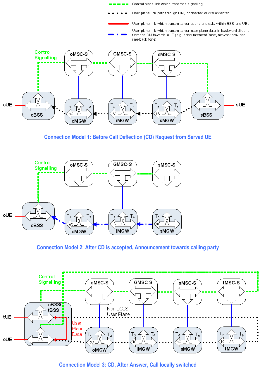
Figure 13.2.6.1.1 shows the network model for Call Deflection (CD).
The oMSC server seizes one context with two bearer terminations in the oMGW. The bearer termination T1 is used for the bearer towards the oBSS (calling subscriber) and the bearer termination T2 is used for the bearer towards the GMSC selected iMGW. The GMSC server seizes one context with two bearer terminations in the iMGW. The bearer termination T4 is used for the bearer towards the sMSC server selected sMGW and the bearer termination T3 is used for the bearer towards the preceding oMGW. The sMSC server seizes one context with two bearer terminations in the sMGW. The bearer termination T5 is used for the bearer towards the GMSC selected iMGW and bearer termination Ts is used for the bearer towards the sBSS (served subscriber).
After a call deflection request is accepted the sMSC server replaces the bearer termination for the served mobile subscriber Ts with the bearer termination for the forwarded-to subscriber T6 in an existing context in the sMGW.
The tMSC server seizes one context with two bearer terminations in the tMGW. The bearer termination T7 is used for the bearer towards the sMSC selected sMGW and bearer termination T8 is used for the bearer towards the tBSS (forwarded-to subscriber).

13.2.6.2 Basic Sequence p. 134
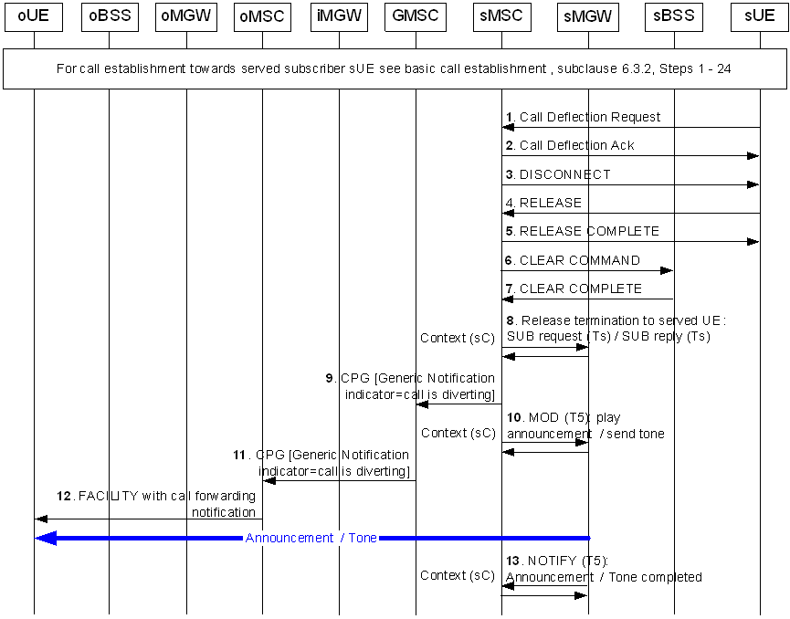
Figure 13.2.6.2.1 and Figure 13.2.6.2.2 show the message sequence example for the call deflection with a possible notification to the calling party using an announcement. In the example the sMSC server optionally requests the sMGW to play an announcement and to notify the announcement completion. The sMSC server requests the establishment of the call and the bearer towards the forward-to subscriber after the possible announcement has completed. In this example the calling subscriber (oUE) and the forwarded-to subscriber (tUE) belong to the same BSS (marked as oBSS and tBSS) and the CN permits LCLS. This example is based on examples from clause 6.

Step 1.
The incoming call is offered to the served subscriber as a basic mobile terminated call as described in the first part of clause 6.3.2. The Call Deflection (CD) supplementary service is active and a Call Deflection is requested from the served subscriber sUE.
Step 2.
The Call Deflection is accepted.
Step 3.
The sMSC server initiates call clearing towards the sUE by sending a DISCONNECT message.
Step 4.
Upon receiving the DISCONNECT message the sUE sends a RELEASE message to the core network.
Step 5.
The sMSC server sends the RELEASE COMPLETE message to the sUE.
Step 6.
The sMSC server request the sBSS to release the associated dedicated resource(s) by sending CLEAR COMMAND message.
Step 7.
The sBSS informs the sMSC server that the associated dedicated resource(s) has been successfully cleared with the CLEAR COMPLETE message.
Step 8.
The sMSC server orders the sMGW to remove the bearer termination (Ts) towards the served mobile subscriber (in case when the radio resources had already been allocated in the sMGW).
Step 9.
The sMSC server sends the CPG message with the Generic Notification Indicator parameter set to "Call is diverting".
Step 10.
The sMSC server provides the sMGW with the announcement/tone identification and requests the sMGW to notify the announcement/tone completion using the Play Announcement or Send Tone procedure.
Step 11.
The GMSC server forwards the CPG message with the Generic Notification Indicator parameter set to "Call is diverting" to the preceding node.
Step 12.
The oMSC server notifies the calling user (oUE) about call forwarding.
Step 13.
The sMGW notifies the sMSC server when the announcement/tone is completed using the Announcement Completed or Tone Completed procedure.

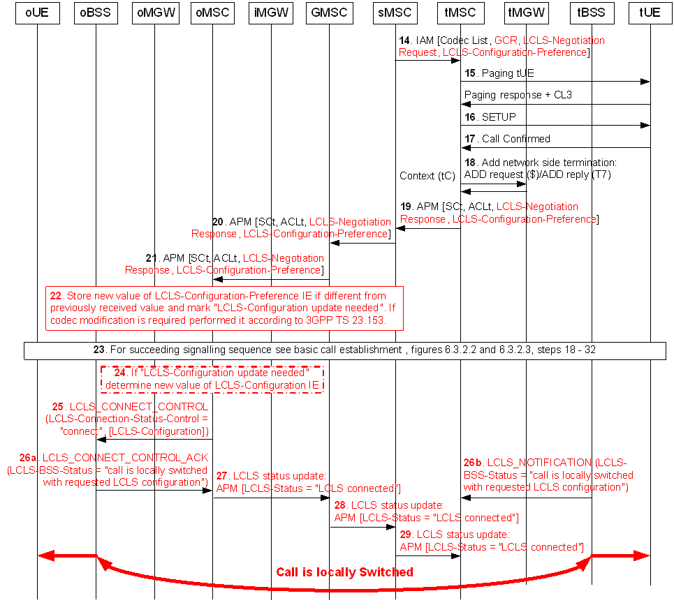
Figure 13.2.6.2.2: CD, Call Establishment Flow (continuation of Figure 13.2.6.2.1)
(⇒ copy of original 3GPP image)
(⇒ copy of original 3GPP image)
Step 14.
If the sMSC server supports LCLS it may modify the LCLS-Negotiation Request IE and the LCLS-Configuration-Preference IE before sending the IAM message containing the GCR with the encapsulated oBSS ID, the LCLS-Negotiation Request IE and the LCLS-Configuration-Preference IE.
Step 15.
The tMSC server pages the forwarded-to subscriber (tUE).
Step 16.
The tMSC server performs call Setup.
Step 17.
The tUE confirms the call.
Step 18.
The tMSC server requests the tMGW to prepare for the network side bearer establishment (T7).
Step 19.
After the tMGW has replied with the bearer address and the binding reference the tMSC server returns the APM message with the selected codec and if LCLS is supported, the LCLS-Negotiation Response IE and the LCLS-Configuration-Preference IE.
Step 20.
The sMSC server transfers the APM message with the LCLS-Negotiation Response IE and the LCLS-Configuration-Preference IE. If codec modification is required then the sMSC server includes the codec related information within the same APM message.
Step 21.
The GMSC server transfers the APM message.
Step 22.
Based on the returned LCLS-Negotiation Response IE IE and the LCLS-Configuration-Preference IE the oMSC server determines whether LCLS is allowed in the core network and if LCLS-Configuration update is needed.
If codec modification is required then the oMSC server performs codec negotiation according to TS 23.153.
Step 23.
When performing further call establishment the procedure between the calling subscriber (oUE) and the forwarded-to subscriber (tUE) is the same as specified in steps 18 - 32 of Figure 6.3.2.1.
Step 24.
Since the received ANM message indicated "LCLS is feasible but not yet connected" the oMSC server checks if LCLS-Configuration updated is needed and if so the oMSC server calculates the new LCLS-Configuration value based on the latest received LCLS-Negotiation IE.
Step 25.
The oMSC server requests the oBSS to connect LCLS and if configuration updated is needed, it includes the LCLS-Configuration IE in the LCLS_CONNECT_CONTROL message.
Step 26a.
Since the BSS has received the through connect request for both call legs the oBSS returns the LCLS_CONNECT_CONTROL_ACK message with the LCLS-BSS-Status IE set to "the call is locally switched with requested LCLS configuration".
Step 26b.
Since the BSS has received the through connect request for both call legs the tBSS signals the LCLS status change by sending the LCLS_NOTIFICATION message with the LCLS-BSS-Status IE set to "the call is locally switched with requested LCLS configuration".
Step 27.
The oMSC server signals the change of the LCLS status through the Core Network by sending the APM message with the LCLS-Status IE set to "LCLS connected".
Step 28.
The iMSC server transfers the change of the LCLS status to the sMSC server.
Step 29.
The sMSC server transfers the change of the LCLS status to the tMSC server.
13.3 Line identification Services p. 136
13.3.1 Calling Line Identification Presentation (CLIP) p. 136
No impact. The line identification related services are signalling based and there are no LCLS related requirements for the Calling Line Identification Presentation (CLIP) service.
13.3.2 Calling Line Identification Restriction (CLIR) p. 136
No impact. The line identification related services are signalling based and there are no LCLS related requirements for the Calling Line Identification Restriction (CLIR) service.
13.3.3 Connected Line Identification Presentation (COLP) p. 136
No impact. The line identification related services are signalling based and there are no LCLS related requirements for the Connected Line Identification Presentation (COLP) service.
13.3.4 Connected Line Identification Restriction (COLR) p. 137
No impact. The line identification related services are signalling based and there are no LCLS related requirements for the Connected Line Identification Restriction (COLR) service.