Content for TS 23.284 Word version: 18.0.0
1…
4…
4.2…
4.3…
5
6…
6.3…
6.3.2
6.3.3
6.3.4
6.3.5
7…
7.2.4…
7.2.4.2
7.2.4.3
7.2.4.4
7.2.4.5
7.2.4.6
7.3…
7.3.4…
7.3.4.2
7.3.4.3
7.3.4.4
8…
8.2.3
8.3…
8.3.2
8.4…
8.4.1.1.7…
8.4.1.2…
8.4.2…
8.4.2.2…
8.4.5…
8.4.5.6
8.4.5.7
8.4.5.8…
9…
13…
13.4…
13.4.3…
13.4.4…
13.5…
13.6…
13.7…
14…
16…
A…
A.2…
4 Main Concepts p. 12
4.1 General p. 12
Local Call Local Switch provides the capability for the user plane to be locally switched (e.g. voice data in user plane is not backhauled to the CS core network) for calls that are generated and terminated by users that are served by the same BSS. The result is saving on transmission resource of the Abis and/or A interface.
Local Call Local Switch shall only be considered for a CS voice call and is transparent to the end user.
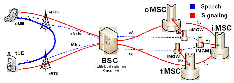
Figure 4.1.1 shows an example of Local Call Local Switching. It highlights only the main nodes and interfaces and differentiates between "originating" nodes and interfaces (oUE, oBTS, oMSC, oMGW, oAbis, oA) and "terminating" nodes and interfaces (tMSC, tMGW, tBTS, tUE, tAbis, tA). It also includes an Intermediate MSC server and MGW (iMSC, iMGW), which may be a (G)MSC server or other intermediate CN control node and its MGW.

The "active" User Plane path is shown with a thick, solid blue line for the case that Local Switching is provided between two BTS's, while the "inactive" User Plane path, i.e. the two Abis-links, the two A-links and the links within the Core Network are not carrying traffic and are therefore marked with thin, dotted blue lines. The Control Plane paths are shown in solid red lines.
Local Call Local Switch is attempted to be instantiated during call establishment. During this phase, negotiation for support of LCLS is performed within the Core Network and requests to correlate and connect the call legs are made to the BSS when LCLS is successfully negotiated. Interaction with existing supplementary services and handover/relocation are supported. Depending on the scenario this may require a break of an existing locally switched call where the voice data on user plane shall be routed via the core network, or a (re)establishment of a locally switched call where the voice data on user plane shall be locally switched in the BSS.
Local Call Local Switch may be supported on both TDM based A interface (AoTDM) and IP based A interface (AoIP).
Local Call Local Switch may be implemented on both a BICC based CS core network and a SIP-I based CS core network and therefore the main concepts that are defined within TS 23.205 and TS 23.231 respectively, also apply to Local Call Local Switch.
The MSC server is in charge of call control, supplementary services and gives permission (or denies) as to whether local switching may be applied. When the MSC server has granted the permission to apply LCLS, the BSC makes the final operation decision whether to establish LCLS (dependent on alignment of codecs, BTS's supporting local switching, resource available, status of its BTS's, the state of its radio legs).