Content for TS 23.284 Word version: 18.0.0
1…
4…
4.2…
4.3…
5
6…
6.3…
6.3.2
6.3.3
6.3.4
6.3.5
7…
7.2.4…
7.2.4.2
7.2.4.3
7.2.4.4
7.2.4.5
7.2.4.6
7.3…
7.3.4…
7.3.4.2
7.3.4.3
7.3.4.4
8…
8.2.3
8.3…
8.3.2
8.4…
8.4.1.1.7…
8.4.1.2…
8.4.2…
8.4.2.2…
8.4.5…
8.4.5.6
8.4.5.7
8.4.5.8…
9…
13…
13.4…
13.4.3…
13.4.4…
13.5…
13.6…
13.7…
14…
16…
A…
A.2…
8.4.5.6 Example BSS Internal Handover that Breaks Local Switching p. 122
8.4.5.6.1 Connection Model p. 122
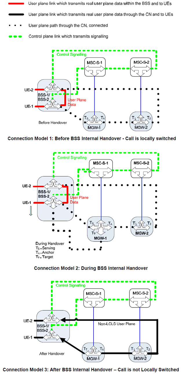
Figure 8.4.5.6.1.1 shows the network model for the Intra-MSC BSS Internal Handover, where the call leg pertinent to the UE-1 is handed over from the serving BSS-1 to BSS-2. BSS-1 is the same as BSS-2 for BSS Internal Handover. The bearer termination T2 is used for the bearer towards BSS-2, which is not affected by this handover. Bearer termination TS is used for the bearer towards BSS-1 and the bearer terminations T1 and TA are used for the bearer towards the succeeding/preceding MGW. Bearer termination TT is for the bearer termination towards the BSS after internal handover. The colours and line types used in the figure are defined differently from TS 23.205 to indicate LCLS specific issues.

Figure 8.4.5.6.1.1: BSS Internal Handover Connection Model that Breaks Local Switching
(⇒ copy of original 3GPP image)
(⇒ copy of original 3GPP image)
8.4.5.6.2 Basic Sequence for BSS Internal Handover that Breaks Local Switching p. 123
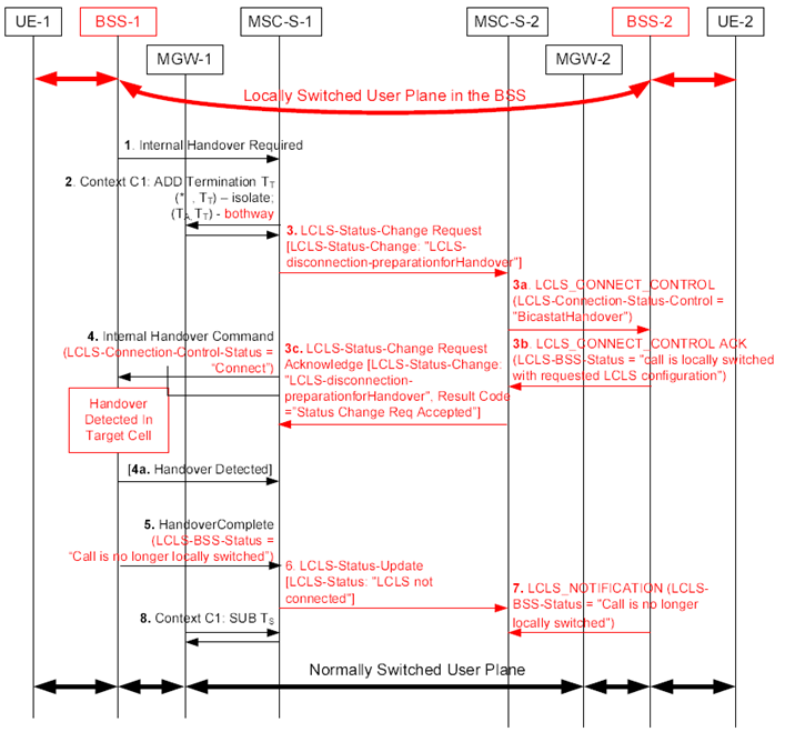
Figure 8.4.5.6.2.1 shows the message sequence example for the BSS Internal Handover that Breaks Local Switching.
In the example, the MSC server receives the Internal Handover Required message and requests the MGW to reserve an RTP bearer termination (TT) using the Reserve and Configure RTP Connection Point procedure with specific flow directions.

Figure 8.4.5.6.2.1: BSS Internal Handover for AoIP that Breaks Local Switching
(⇒ copy of original 3GPP image)
(⇒ copy of original 3GPP image)
Step 1 - 2.
As for normal Internal Handover, see clause 8.4.5 of TS 23.205.
Step 3.
MSC-1 Server indicates preparation for disconnection due to handover through the Core Network.
Step 3a.
MSC-2 Server indicates to BSS-2 to start UL bicasting.
Step 3b.
The BSS-2 sends the LCLS_Connect_Control_Ack message with the LCLS-BSS-Status IE set to "the call is locally switched with requested LCLS configuration".
Step 3c.
MSC-2 Server sends LCLS-Status-Change-Request-Acknowledgement.
Step 4.
The MSC-1 Server determines that local switching is permitted by the core network and sends the Internal Handover Command message, optionally including the LCLS-Connection-Control-Status message indicating "Connect".
Step 4a.
BSS-1 may indicate Handover Detected.
Step 5.
BSS-1 sends the Handover Complete message to MSC-1 Server to indicate LCLS-BSS-Status is set to "Call is no longer locally switched".
Step 6.
MSC-1 Server propagates the change of the LCLS Status through the Core Network.
Step 7.
BSS-2 indicates that the call is no longer locally switched in the LCLS_NOTIFICATION message.
Step 8.
The old termination (TS) is removed and the call is normally switched through the Core Network.