Content for TS 22.104 Word version: 19.2.0
0f…
4…
5…
5.3…
6…
A…
A.2.2…
A.2.2.4…
A.2.3…
A.4…
A.4.4…
A.4.4.3…
A.4.5…
A.4.8…
A.5…
A.6…
B…
C…
C.3
C.4…
C.5
D…
E…
E Audio and Video Production
E.1 Description
E.2 Multiple source wireless studio
E.3 Timing use in AV production applications
F Relation of reliability and communication service availability
$ Change history
E Audio and Video Production |R17| p. 99
E.1 Description p. 99
AV production includes television and radio studios, outside and remotely controlled broadcasts, live newsgathering, sports events, music festivals, among others. All of these applications require a high degree of reliability, since they are related to the capturing and transmission of data at the beginning of a production chain. This differs drastically when compared to other multimedia services because the communication errors will be propagated to the entire audience that is consuming that content both live and recorded for later distribution. Furthermore, the transmitted data is often post-processed with nonlinear filters which could actually amplify defects that would be otherwise not noticed by humans. Therefore, these applications call for uncompressed or only slightly compressed data, and very low probability of errors. These devices will also be used alongside existing technologies which have a high level of performance and so any new technologies will need to match or improve upon the existing workflows to drive adoption of the technology.
The performance aspects that are covered by/in TS 22.263 (Service requirements for Video, Imaging and Audio for professional applications) also target the latency that these services experience.
In recent years production facilities have moved from bespoke unidirectional highly specialised networks to IP based systems and software-based workflows. This migration is expected to continue, and wireless IP connectivity is key to a number of these workflows.
Typical set ups require multiple devices such as cameras, microphones and control surfaces that require extremely close synchronisation to maintain consistency of pictures and audio. Such clock synchronization requirements are captured in clause 5.6. Often devices need to communicate directly to each other for instance a camera to a monitor or a microphone to a PA system.
Video and audio applications also require extremely high quality of service metrics as the loss of a single packet can cause picture or sound breakup in the downstream processing or distribution. Often this is a legal, regulatory or contractual agreement to maintain a high quality, stable and clear video or audio signal.
E.2 Multiple source wireless studio p. 99
This use case will deploy a multiple camera studio of approximately 1,000 m² (~5 cameras) where wired and wireless functionalities currently provided by traditional infrastructure technologies are likely to be deployed using a standalone non-public network. A combination of IP enabled wired and wireless cameras working at both HD and UHD resolutions will be deployed in a studio. Associated equipment such as video monitors, prompting systems, camera control will be provided over the 5G network. Camera timing and synchronisation will be provided over the 5G system. As well as video, audio will be sourced from both wired and wireless microphones incl. control/monitoring and combined with the video to produce high quality synchronised AV content. 5G will also be deployed to control lighting and camera robotics. Talkback intercom systems will be deployed using low latency multicast links.
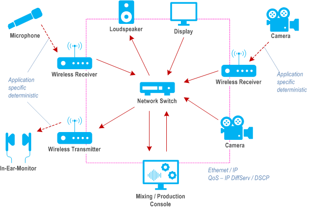
Today's digital AV network transport is typically handled separately for wireless and wired transfers (see Figure E.2-1). Wireless AV transmissions are implemented with application specific solutions that allow deterministic data transport of a single isolated audio or video link. Wired AV transmissions are Ethernet / IP based. Quality of service in AV IP networks is mainly achieved with IP DiffServ / DSCP based prioritization of packets in network switches. This method is sufficient for most AV use cases since jitter resulting from packet collisions is small, for example in the order of 10 μs per concurring data stream in Gbit Ethernet.

The microphones and cameras can be co-located in a broadcast centre in which case they would communicate through a LAN or NPN. For remote production operations the mixing and production console may be separated by some distance (existing examples are cross continental. In this instance they may communicate via a PLMN or combination of PLMN and WAN networks.
Some approaches may also deploy main (leader) equipment at the broadcast centre with secondary (follower) equipment at the location site to reduce latency.
Other aspects of this workflow may also include robotic control where both the physical position (height, direction and tilt) and the technical control (focus, zoom, iris, colour) of a device of a camera, microphone or light may be controlled remotely. In this instance round trip latency of < 20ms is required in order for an operator to see a move reflected at his control position as it is made.
It is important to note that these are a combination of automated robotics (pre-programmed moves) and manually controlled robotics (following an unpredictable event such a sport).
E.3 Timing use in AV production applications p. 100
Timing of multiple devices such as microphones and camera is also critical. Timing signals are used in 2 separate ways.
- To maintain synchronisation between devices so that electronic shutters on cameras operate at the same time and frequency and that when cutting between any two cameras pointed at the same source no discernible jumps can be seen. This requires accuracy within the frame boundary of a given video signal. A single frame of video at 120 Hz would require a clock accurate to within 8 ms.
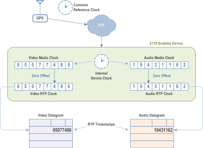
- To timestamp an IP packet carrying a video or audio sample. Existing standards and workflows for AVPROD rely on IEEE 1588 PTP timing with a SMPTE media profile applied. This requires a clock accurate to within 1 μs

F Relation of reliability and communication service availability |R18| p. 102
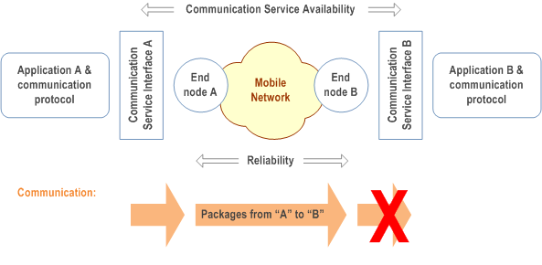
Availability and reliability are used both in 3GPP and vertical industries, but with different meanings. Communication service availability addresses the availability of a communication service. This definition follows the vertical standard IEC 61907 [7]. On the other hand, reliability is a 3GPP term and addresses the availability of a communication network. The relation of both terms is depicted in Figure F-1 for a mobile network.

As depicted, reliability covers the communication-related aspects between two nodes (here: end nodes), while communication service availability addresses the communication-related aspects between two communication service interfaces. This might seem to be a small difference, but this difference can lead to situations, where reliability and communication service availability have different values.
Example:
traffic gets "stuck"
The related scenario is depicted in Figure F-2.

This scenario addresses unicast communication from application A to B. The packets are handed over at the communication service interface A from the application to the communication network, and the packets are then transmitted to the end node B. In this example, the packets received by end node B are not exposed at the communication service interface B. So, even if all packets that are handed over to end node A are successfully delivered to end node B within the time constraint required by the targeted service (reliability = 100 %), the communication service availability is 0% since no packets arrive at the "end", namely the communication service interface B.
Example:
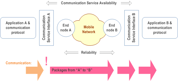
packets dropped at the communication service interface
The related scenario is depicted in Figure F-3.

This scenario describes unicast communication of evenly interspersed packets from application A to B. The packets are handed over at the communication service interface A from the application to the communication network, and the packets are then transmitted to the end node B. However, only every second packet is actually successfully handed over to end node A and then transmitted to end node B. Thus, only half of the packets arrive at application B. Note though that the reliability of the mobile network is 100%, since all packets transmitted by end node A are delivered to end node B within the time constraint required by the targeted service. However, depending on the agreed QoS, the communication service availability can be of the same value as the reliability or much lower. For instance, if the agreed survival time is equal to or larger than the end-to-end latency, reliability and communication service availability are equal. However, if the survival time is smaller, the reliability is two times the communication service availability.
Note that the shortest time interval over which the communication service availability should be calculated is the sum of maximum allowed end-to-end latency and survival time.