Content for TS 22.104 Word version: 19.2.0
0f…
4…
5…
5.3…
6…
A…
A.2.2…
A.2.2.4…
A.2.3…
A.4…
A.4.4…
A.4.4.3…
A.4.5…
A.4.8…
A.5…
A.6…
B…
C…
C.3
C.4…
C.5
D…
E…
C Characterising communication services
C.1 Modelling of communication in automation
C.1.1 Area of consideration
C.1.2 Logical link
C.1.2.1 Nature and function
C.1.2.2 Message transformation
C.1.2.3 Communication device
C.1.2.4 Communication system
C.2 Communication service description
C.2.1 Overview
C.2.2 Characteristic parameters
C.2.3 Influence quantities
...
...
C Characterising communication services p. 83
C.1 Modelling of communication in automation p. 83
C.1.1 Area of consideration p. 83
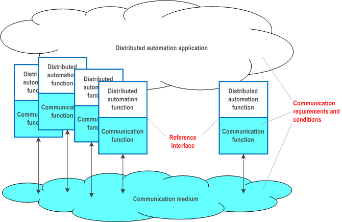
For our discussion of communication in automation we apply a definition of the area of consideration for industrial radio communication that is found elsewhere in the literature [4]. This definition is illustrated in Figure C.1.1-1.

Here, a distributed automation application system is depicted. This system includes a distributed automation application, which is the aggregation of several automation functions. These can be functions in sensors, measurement devices, drives, switches, I/O devices, encoders etc. All of these functions contribute toward the control of physical objects. Field bus systems, industrial Ethernet systems, or wireless communication systems can be used for connecting the distributed functions. The essential function of these communication systems is the distribution of messages among the distributed automation functions. For cyber-physical control applications, the dependability of the entire communication system and/or of its devices or its links is essential. Communication functions are realised by the respective hardware and software implementation.
In order for the automation application system to operate, messages need to be exchanged between spatially distributed application functions. For that process, messages are exchanged at an interface between the automation application system and the communication system. This interface is termed the reference interface. Required and guaranteed values for characteristic parameters, which describe the behavioural properties of the radio communication system, as well as some influence quantities refer to that interface.
The conditions that influence the behaviour of wireless communication are framed by the communication requirements of the application (e.g., end-to-end latency), the characteristics of the communication system (e.g., output power of a transmitter), and the transmission conditions of the media (e.g., signal fluctuations caused by multipath propagation).
General requirements from the application point of view for the time and failure behaviour of a communication system are mostly related to an end-to-end link. It is assumed in the present document that the behaviour of the link is representative of the communication system as a whole and of the entire scope of the application.
C.1.2 Logical link p. 84
C.1.2.1 Nature and function p. 84
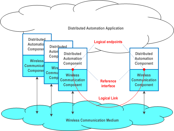
Starting with the general approach mentioned in Subclause C.1.1, the logical link can be regarded as a possible asset within the area of consideration (see Figure C.1.1-1). The conditions under which its functions are to be performed are vital for the dependability of the automation application system.

This is the link between a logical end point in a source device and the logical end point in a target device. Logical end points are elements of the reference interface, which may group several logical end points together.
The intended function of the logical link is the transmission of a sequence of messages from a logical source end point to the correct logical target end point. This is achieved by transforming each message into a form that fosters error-free transmission. The transmission process includes certain processes, for instance repetitions, in order to fulfil the intended function. After transmission, the transported package(s) is converted back into a message. The message is to be available and correct at the target within a defined time. The sequence of messages at the target is to be the same as the sequence at the source.
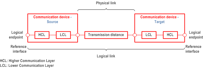
The functional units, which are necessary to fulfil this function are shown, in Figure C.1.2.1-1.

The required function can be impaired by various influences, which can lead to communication errors. Such errors are described elsewhere in the literature [4] [5]. A summary of these errors is provided in Annex A. The occurrence of one of these errors influences the values of the relevant dependability parameters of the logical link.
C.1.2.2 Message transformation p. 85
The present document addresses both OSI-layer-3 (IP) and OSI-layer-2 communication. The model in Figure C.1.2.1-1 can be used for describing both cases. The implementation of communication functions is split between a higher communication layer (HCL) and a lower communication layer (LCL). The partition of the layer for the two traffic options discussed in the present document is provided in Table C.1.2.2-1. This difference is of importance when discussing the implications of the service performance requirements in Clause 5 and Annex A for the network performance (see Clause C.5).
| OSI level at which the traffic occurs | Levels comprised by the higher communication layer | Levels comprised by the lower communication layer |
|---|---|---|
| 3 | 4 to 6 | 1 to 3 |
| 2 | 3 to 6 (note) | 1 to 2 |
|
NOTE:
In some vertical application, level 3 to 6 are not implemented.
|
||
The messages to be transmitted for the intended function of a logical link are defined by strings of characters with a certain semantic. Such a character string is handed over as user data at the reference interface for transmission. If the number of characters in a message is too great for it to be transmitted as a unit, the message is divided for transmission into several packets (fragmentation).
C.1.2.3 Communication device p. 85
The communication devices—together with the physical link—determine the function and thus the dependability of the logical link. The function of the communication devices is the correct sending and correct receipt of sequences of messages. The asset "communication device" is depicted in Figure C.1.2.3-1.

C.1.2.4 Communication system p. 85
The communication system as an asset represents a quantity of logical links whose message transmissions are implemented by wireless devices via one or more media. The communication system function to be provided consists in transmitting messages for all the logical links in the distributed application. This function is to be performed for a defined period, the operating time of the automation application.
In an automation application system, it is paramount that requirements pertaining to logical links are fulfilled. These requirements and the conditions can be very different from one case and implementation to the other. The functions (services and protocols) for individual logical links can therefore also be different. Despite these differences, some of the logical links share communication devices and media.
C.2 Communication service description p. 86
C.2.1 Overview p. 86
Table C.2.2-1 and Table C.2.3-1 summarise candidate interface parameters for the description of the communication service performance. The lists are grouped according to whether the parameter stands for automation characteristic parameters (Table C.2.2-1) or influence quantities (Table C.2.3-1). The meaning of the columns and rows is explained after each table.
C.2.2 Characteristic parameters p. 86
| Parameter name | Typical metric (unit) | Traffic class (note) | ||
|---|---|---|---|---|
| Deterministic periodic communication | Deterministic aperiodic communication | Non-deterministic communication | ||
| Communication service availability | Minimum availability (dimensionless) | X | X | X |
| End-to-end latency | Target value and timeliness (ms) | X | X | X |
| Communication service reliability | Mean time between failures (days) | X | X | X |
| Service bit rate | Target value (bit/s); user experienced data rate (bit/s); time window (s) | – | X | X |
| Update time | Target value and timeliness | X | – | – |
|
NOTE:
application requirements (KPIs). X: applies; –: does not apply.
|
||||
Parameter description
Communication service availability
- This parameter indicates if the communication system works as contracted ("available"/"unavailable" state). The communication system is in the "available" state as long as the availability criteria for transmitted packets are met. The service is unavailable if the packets received at the target are impaired and/or untimely (e.g. update time > stipulated maximum). If the survival time (see Table C.2.3-1) is larger than zero, consecutive impairments and/or delays are ignored until the respective time has expired.
- This parameter indicates the time allotted to the communication system for transmitting a message and the permitted timeliness.
- Mean time between failures is one of the typical indicators for communication service reliability. This parameter states the mean value of how long the communication service is available before it becomes unavailable. For instance, a mean time between failures of one month indicates that a communication service runs error-free for one month on average before an error/errors make the communication service unavailable. Usually, an exponential distribution is assumed. This means, there will be several failures where the time between two subsequent errors is below the mean value (1 month in the example).
- Communication service availability and communication service reliability (mean time between failures) give an indication on the time between failures and the length of the failures.
- deterministic communication The target value indicates committed data rate in bit/s sought from the communication service. This is the minimum data rate the communication system guarantees to provide at any time, i.e. in this case target value = user experienced data rate.
- non-deterministic communication The target value indicates the target data rate in bit/s. This is the information rate the communication system aims at providing on average during a given (moving) time window (unit: s). The user experienced data rate the lower data rate threshold for any of the time windows.
-
Applicable only to periodic communication, the update time indicates the time interval between any two consecutive messages delivered from the egress (of the communication system) to the application.
-
In practice, vertical communication networks serve applications exhibiting a wide range of communication requirements. In order to facilitate efficient modelling of the communication network during engineering, and for reducing the complexity of network optimisation, disjoint QoS sets have been identified. These sets are referred to as traffic classes [6]. Typically, only three traffic classes are needed in industrial environments [6], i.e.
- deterministic periodic communication;
- deterministic aperiodic communication; and
- non-deterministic communication.
- Deterministic periodic communication stands for periodic communication with stringent requirements on timeliness of the transmission.
- Deterministic aperiodic communication stands for communication without a pre-set sending time. Typical activity patterns for which this kind of communication is suitable are event-driven actions.
- Non-deterministic communication subsumes all other types of traffic. Periodic non-real time and aperiodic non-real time traffic are subsumed by the non-deterministic traffic class, since periodicity is irrelevant in case the communication is not time-critical.
Control service request and response; monitoring service response and indication.
C.2.3 Influence quantities p. 88
| Parameter name | Typical metric (unit) | Traffic class (note) | Usage of this parameter | ||||||
|---|---|---|---|---|---|---|---|---|---|
| Deterministic periodic communication | Deterministic aperiodic communication | Non-deterministic communication | |||||||
| Burst | Maximum user data length (byte) and line rate of the communication service interface (bit/s) | – | X | X | Service request and response; monitoring service response and indication | ||||
| Message size | Maximum or current value (byte) | X | (X) | (X) | Service request and response; non-deterministic data transmission; deterministic aperiodic data transmission | ||||
| Service time interval | Start (time) and end (time) | X | X | X | Service request and response | ||||
| Survival time | Maximum (s) | X | X | – | Service request and response | ||||
| Transfer interval | Target value and timeliness (s) | X | – | – | Service request and response | ||||
|
NOTE:
X: applies; (X): usually does not apply; –: does not apply.
|
|||||||||
Parameter description
Burst
The transmission of, for instance, program code and configuration data may be handed to the 3GPP system as data burst. In this case, the ingress data rate exceeds the capacity of the network, which implies that some of the data has to be stored within the ingress node of the communication system before it can be transmitted to the egress interface(s). However, the application consuming the communication service requires that the data of such a burst needs to be transmitted completely. This is in contrast to periodic data transmission, where new messages overwrite old ones.
Typical metrices for bursts: maximum user data length and line rate of the communication service interface.
Message size
The user data length indicates the (maximum) size of the user data packet delivered from the application to the ingress of the communication system and from the egress of the communication system to the application. For periodic communication this parameter can be used for calculating the requested user-experienced data rate. If this parameter is not provided, the default is the maximum value supported by the PDU type (e.g. Ethernet PDU: maximum frame length is 1,522 octets, IP PDU: maximum packet length is 65,535 octets).
Service time interval
Describes the start and end time of a communication service. Note that there are other ways to describe the service time interval numerically, for instance as the tuple [start time, service duration].
Survival time
The maximum survival time indicates the time period the communication service may not meet the application's requirement before the communication service is deemed to be in an unavailable state.
Transfer interval
Applicable only to periodic communication, the transfer interval indicates the time elapsed between any two consecutive messages delivered by the automation application to the ingress of the communication system.