Content for TS 22.104 Word version: 19.2.0
0f…
4…
5…
5.3…
6…
A…
A.2.2…
A.2.2.4…
A.2.3…
A.4…
A.4.4…
A.4.4.3…
A.4.5…
A.4.8…
A.5…
A.6…
B…
C…
C.3
C.4…
C.5
D…
E…
C.5 Communication service terminology w.r.t. 5G network and vertical applications p. 93
This section clarifies the wording and terminology with respect to communication interfaces that are relevant for vertical applications. Because the 3GPP network does not cover the complete ISO-OSI communication stack, it is important to distinguish between
- the vertical applications' point of view, and
- the 3GPP network's point of view.

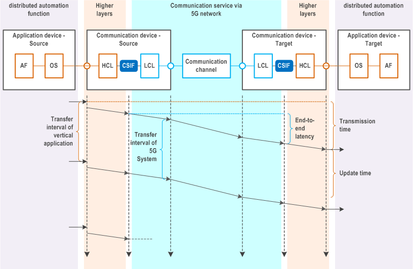
Figure C.5-2 illustrates how messages are transmitted from a source application device (e.g., a programmable logic controller) to a target application device (e.g. an industrial robot). The source application function (AF) is executed in the source operating system (OS) and hands over a message to the application layer interface of the source communication device. In the higher communication layers (HCL), which are not part of the 3GPP system, the data is processed. From the HCL the data is transferred to the lower communication layers (LCL), which are part of the 3GPP system. After transmission through the physical communication channel and the LCL of the target communication device, the data is passed to the HCL and lastly to the target application device. Characteristic parameters with respect to time are defined in Figure C.5-2.
From 3GPP system point of view:
- Transfer interval of 5G system: Time between the arrival of two pieces of data at the source CSIF.
- End-to-end latency: Time measured from the point when a piece of data received at the CSIF in the source communication device until the same piece of data is passed to the CSIF in the target communication device.
- Transfer interval of vertical application: Time between the transmission of two successive pieces of data from the source application.
- Transmission time: Time measured from the point when a piece of data is handed from the application layer interface of the source application device, until the same piece of data is received at the application layer interface of the target application device.
- Update time: Time between the reception of two consecutive pieces of data at the application layer interface to the target application device.
