Content for TR 38.799 Word version: 19.0.0
4 Wireless Access Backhaul (WAB)
4.1 General
4.2 WAB Architecture
4.3 Operational aspects
4.3.1 WAB-node integration procedure
4.3.2 WAB authorization
4.3.3 Configuration of WAB-node
4.3.3.1 General
4.3.3.2 IP address configuration for WAB-gNB
4.3.3.3 TAC/RANAC (re-)configuration for WAB-gNB's cell
4.3.4 Mobility handling
4.3.4.1 General
4.3.4.2 WAB-MT mobility
4.3.4.2.1 General
4.3.4.2.2 The BH-UPF remains unchanged as the WAB-MT moves inside a PLMN
4.3.4.2.3 BH-UPF changes as the WAB-MT moves inside a PLMN
4.3.4.2.4 Roaming of the WAB-MT
4.3.4.3 WAB-gNB mobility
4.3.4.3.1 General
4.3.4.3.2 WAB-gNB mobility without change of UE's AMF(s)
4.3.4.3.3 WAB-gNB mobility with change of UE's AMF(s)
4.3.4.3.3.1 General
4.3.4.3.3.2 Solution with two logical WAB-gNBs
4.3.4.3.3.3 Solution with single logical WAB-gNB
4.3.5 Resource multiplexing
...
...
4 Wireless Access Backhaul (WAB) p. 7
4.1 General p. 7
The study is based on the following requirements:
- The WAB-node includes a gNB component (WAB-gNB) and an MT component (WAB-MT).
- The WAB-gNB is based on the gNB functionality specified in TS 38.300 and TS 38.401.
- The CU-DU split of the WAB-gNB is not considered in this study.
- The WAB-MT supports at least a subset of UE functionalities.
- The NR Uu is used for the radio link between WAB-gNB and the served UEs.
- The NR Uu radio link between the WAB-gNB and the served UEs does not use NTN.
- The study focuses on NR-Uu backhaul.
- In-band scenario for access and backhaul is not precluded to be studied.
- The study precludes the scenario where the access and the backhaul are in-band while the backhaul uses NTN.
- The study focuses on the use of WAB-MT's PDU session via NR Uu as backhaul of WAB-gNB. Other options for the backhaul (including non-3GPP radio technology) are not precluded but are not a part of the study.
- A WAB-gNB cannot serve WAB-MT(s).
- The study includes a scenario where the WAB-gNB and the WAB-MT connect to the same PLMN or to different PLMNs.
- The WAB-MT may connect to a public PLMN or an SNPN.
- The WAB-gNB may connect to a public PLMN or an SNPN.
- Legacy UEs can connect to the WAB-gNB. There are no WAB-specific enhancements for UEs that connect to the WAB-gNB.
4.2 WAB Architecture p. 8
Figure 4.2-1 shows an example of WAB architecture for 5GS when the WAB-gNB's NG traffic is transported via PDU session backhaul.
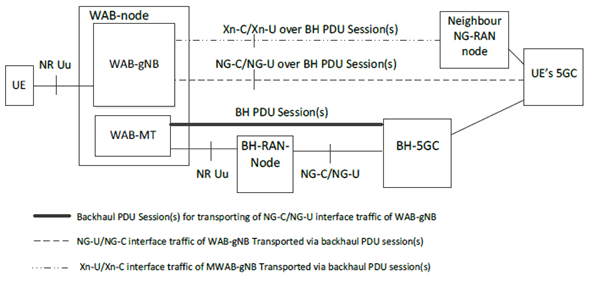
Figure 4.2-1: The WAB architecture example for 5GS when the WAB-gNB traffic is transported via PDU session backhaul
(⇒ copy of original 3GPP image)
(⇒ copy of original 3GPP image)
The neighbour NG-RAN node can be a BH-RAN-node, or a surrounding NG-RAN node. The WAB-gNB's OAM traffic can also be transferred over the BH PDU session(s).
Figure 4.2-2 shows an example of WAB architecture for 5GS when the WAB-gNB's NG traffic is transported via non-3GPP backhaul:
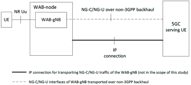
Figure 4.2-2: The WAB architecture example for 5GS when the WAB-gNB traffic is transported via non-3GPP backhaul
(⇒ copy of original 3GPP image)
(⇒ copy of original 3GPP image)
Figure 4.2-3 shows protocol stack examples of NG Control plane and User plane transport for a UE connected to the network via a WAB-node.
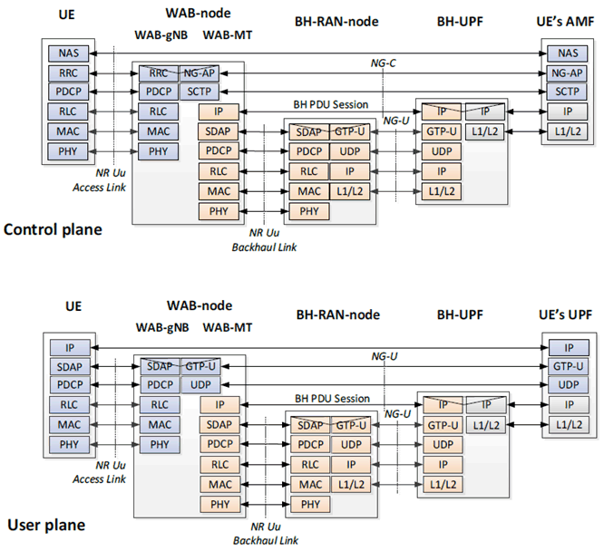
Figure 4.2-3: Protocol stack examples of NG Control plane and User plane transport for a UE connected via WAB-node
(⇒ copy of original 3GPP image)
(⇒ copy of original 3GPP image)
Figure 4.2-4 shows protocol stack examples of Xn Control plane and User plane transport for WAB-node.
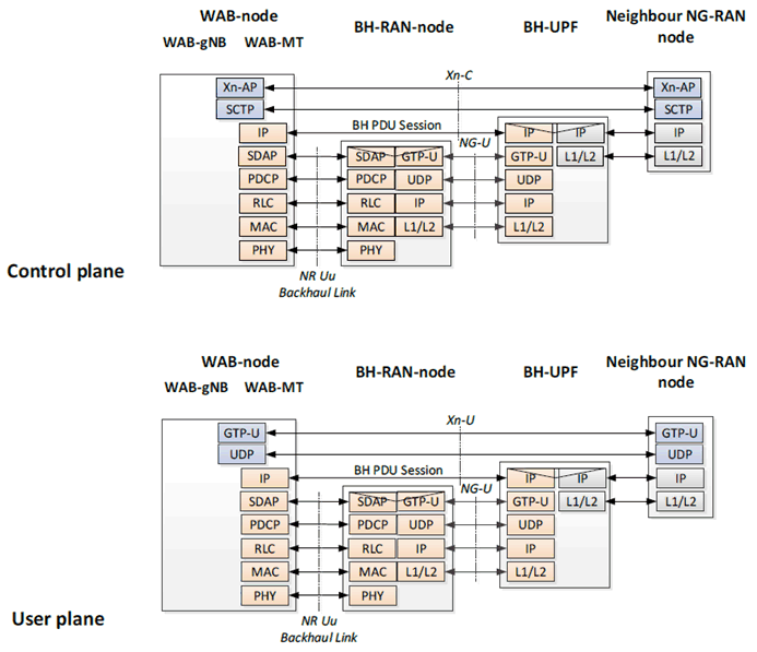
Figure 4.2-4: Protocol stack examples of Xn Control plane and User plane transport
(⇒ copy of original 3GPP image)
(⇒ copy of original 3GPP image)
Figure 4.2-5 shows an example of WAB architecture for using an L2TP tunnel gateway (LNS) for WAB-gNB's traffic over the BH PDU session(s).
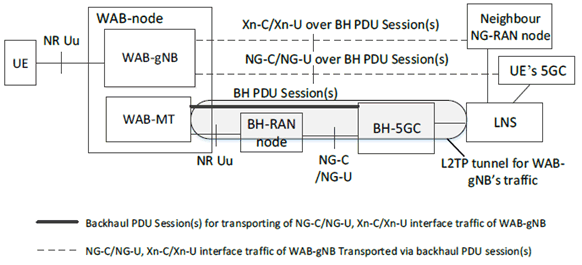
Figure 4.2-5: The WAB architecture example for 5GS using an L2TP tunnel gateway to convey the WAB-gNB's traffic over the BH PDU session(s)
(⇒ copy of original 3GPP image)
(⇒ copy of original 3GPP image)
Figure 4.2-6 shows protocol stack examples for NG Control plane and User plane transport using an L2TP tunnel.
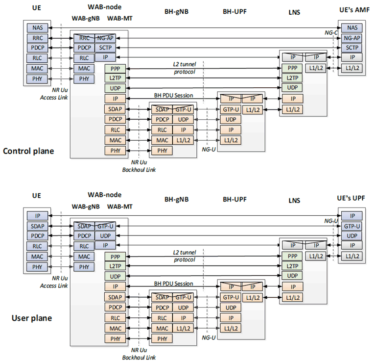
Figure 4.2-6: The protocol stack for NG-U and NG-C transport using L2TP tunnel over BH PDU session(s)
(⇒ copy of original 3GPP image)
(⇒ copy of original 3GPP image)
The solutions using L2TP shown in Figures 4.2-5 and 4.2-6 do not guarantee inter-vendor interoperability since support of L2TP is not mandated for NG and Xn. Therefore, these solutions are out-of-scope of this study.
4.3 Operational aspects p. 13
4.3.1 WAB-node integration procedure p. 13

Phase 1:
WAB-MT setup. The WAB-MT of a WAB-node connects to the network in the same way as a UE by performing RRC connection setup procedure with the BH-RAN-node. The WAB-MT then performs, authorization and authentication with the BH-5GC. After the WAB-MT is authorized, the WAB-MT can establish one or more PDU sessions for backhauling.
Phase 2:
WAB-gNB setup. This phase includes the following 3 sub-phases:
Sub-phase 2-1:
WAB-gNB initialization. In this phase, the WAB-gNB is configured by the OAM (e.g., with the information of AMF(s) to serve the UE) and service-authorized by the SeGW or by the OAM.
Sub-phase 2-2:
NG connection setup. The WAB-gNB establishes NG connection(s) toward the AMF(s). This step may follow legacy procedures. After the NG is set up, the WAB-gNB can start serving UE(s).
Sub-phase 2-3:
Xn connection setup. If needed, the WAB-gNB may establish Xn connection(s) towards the BH-RAN-node and/or other NG-RAN node(s).
4.3.2 WAB authorization p. 13
WAB authorization includes the authorization of the WAB-MT and the service authorization of the WAB-gNB. The authorization of the WAB-MT is different from the service authorization/configuration/activation of the WAB-gNB.
Authorization of the WAB-MT provides the WAB-MT with the right to support backhauling the traffic of the co-located WAB-gNB via BH PDU session(s).
Authorization of the WAB-gNB provides the service authorization, i.e., the right to serve UEs. The service authorization of the WAB-gNB is performed by e.g., OAM/SeGW using legacy procedures.
The WAB-gNB's service authorization status may change. In case the WAB-gNB's service authorization status changes from "authorized" to "not authorized", the UEs served by the WAB-gNB can either be handed over to other RAN nodes or they can be released, after which the NG and Xn connection(s) of the WAB-gNB can be removed.
4.3.3 Configuration of WAB-node p. 13
4.3.3.1 General p. 13
Certain configurations of the WAB-node may need to be updated as the node moves, e.g.:
- The parameters that enable the WAB-gNB to select and connect to the AMF(s) to serve the UE(s).
- The parameters that enable the WAB-gNB to connect to, and communicate with, the OAM system.
- The configuration parameters that the WAB-gNB should broadcast, e.g., the TAC(s), the cell ID(s), the RANAC(s).
4.3.3.2 IP address configuration for WAB-gNB p. 14
A WAB-MT obtains IP address(es) for the PDU sessions in the same manner as a legacy UE.
The WAB-gNB can use the IP address(es) of the WAB-MT for the PDU sessions that backhaul the NG, Xn and OAM traffic. The WAB-gNB supports security protection of NG and Xn via IPsec, as defined by TS 33.501.
In case the WAB-gNB uses the IPsec tunnel mode to protect the OAM, NG and/or Xn traffic, the allocation of the inner tunnel IP address(es) is outside of 3GPP scope.
It is possible to transport OAM, NG or Xn traffic over other types of tunnel protocols on top of the WAB-MT's PDU session(s), e.g., such as L2TP. In this case, the WAB-gNB uses different IP address(es) from WAB-MT. Since the support of these tunnel protocols is not defined for NG and/or Xn, such tunnel protocols are out-of-scope of this study.
4.3.3.3 TAC/RANAC (re-)configuration for WAB-gNB's cell p. 14
The TAC/RANAC of WAB-gNB's cell is configured by the OAM, and it can be reconfigured by the OAM during the mobility of WAB-node. The TAC/RANAC of the WAB-gNB's cell may be the same as, or different than, the TAC/RANAC of the co-located WAB-MT's serving cell. The TAC/RANAC broadcast by the WAB-gNB's cell can be changed in order to reflect the WAB-node's physical location.
4.3.4 Mobility handling p. 14
4.3.4.1 General p. 14
The following scenarios for WAB-node mobility are supported:
- The UE's AMF/UPF remains unchanged as the WAB-gNB moves.
- The UE's AMF/UPF changes as the WAB-gNB moves.
- The BH-UPF/-AMF remains unchanged as the WAB-MT moves inside a PLMN.
- The BH-UPF/-AMF changes as the WAB-MT moves inside a PLMN.
4.3.4.2 WAB-MT mobility p. 14
4.3.4.2.1 General p. 14
The WAB-MT reuses legacy mobility handover procedures for the UE as it moves throughout the BH-RAN.
4.3.4.2.2 The BH-UPF remains unchanged as the WAB-MT moves inside a PLMN p. 14
In case the WAB-MT's PSA UPF does not change during these mobility procedures, the IP addresses allocated for the WAB-MT's PDU sessions do not change. Therefore, the NG and Xn connections of the WAB-gNB carried over the BH PDU session(s) remain unaffected.
4.3.4.2.3 BH-UPF changes as the WAB-MT moves inside a PLMN p. 15
When the WAB-MT's PSA UPF need to be changed due to WAB-MT's mobility, new BH PDU session(s) need to be established reusing existing mechanisms defined in TS 23.501/TS 23.502. In this case, the (outer) IP addresses used by the WAB-gNB for the transport of NG and Xn connections of the WAB-gNB will change.
4.3.4.2.4 Roaming of the WAB-MT p. 15
During WAB-node movement, the WAB-MT may connect to a PLMN different than its HPLMN.
4.3.4.3 WAB-gNB mobility p. 15
4.3.4.3.1 General p. 15
During WAB-node movement, establishment, and removal of the WAB-gNB's NG and/or Xn connections may be needed.
Establishment of Xn connections of the WAB-gNB with BH-RAN nodes, as well as with surrounding RAN nodes, is supported, and it can follow legacy procedures.
4.3.4.3.2 WAB-gNB mobility without change of UE's AMF(s) p. 15
During WAB-node movement, radio configuration parameters of the WAB-gNB may be changed (e.g., cell ID, PCI and/or TAC) without the change of the UE's AMF(s). This change of radio configuration parameters may require the UE handling by means of, e.g., intra-gNB handover and/or Mobility Registration Update as defined in TS 23.502.
4.3.4.3.3 WAB-gNB mobility with change of UE's AMF(s) p. 15
4.3.4.3.3.1 General p. 15
Due to WAB-node movement, the change of UE's AMF(s) may be needed, based on, e.g., WAB-node's current location and/or additional criteria. The NG connection handling and WAB-gNB configuration update may affect the served UEs.
4.3.4.3.3.2 Solution with two logical WAB-gNBs p. 15
The steps for the solution with two logical WAB-gNBs are as follows:
- The WAB-node may obtain the configuration parameters needed to establish the connection to the UE's new AMF(s).
- A new logical WAB-gNB is instantiated, and it establishes NG connection(s) towards one or more new AMF(s).
- The new logical WAB-gNB may activate one or more new cells, with new cell configuration parameters related to the WAB-gNB's current location. The new cells may broadcast the radio parameters configured for the new AMF(s), e.g., TAC, etc. The old cell(s) remain(s) active.
-
The UEs are handled as follows:
- A UE in RRC_CONNECTED state is handed over between an old cell served by the old logical WAB-gNB and a new cell served by the new logical WAB-gNB via NG-based handover with AMF relocation, as defined in TS 23.502. When all UEs in RRC_CONNECTED state have been handed over, the old cell(s) are removed from service.
- A UE in RRC_IDLE or RRC_INACTIVE state camping on the old cell(s) reselects a new cell, and legacy procedure (e.g., Mobility Registration Update procedure as defined in TS 23.502) is performed.
- The NG connection(s) between the old logical WAB-gNB and the initial AMF(s) are removed and the WAB-gNB is removed from service.
4.3.4.3.3.3 Solution with single logical WAB-gNB p. 16
It may be possible to support the change of UE's AMF(s) with a single logical WAB-gNB on the WAB-node. The following options may be considered, their feasibility and the impact on CN needs to be confirmed with SA2, and potentially RAN2 if needed.
Option 1: Single WAB-gNB with a single cell using mobility registration update due to TAC change
In this option, the WAB-gNB establishes a new NG connection towards the new AMF and concurrently maintains NG connections to both AMFs. The WAB-gNB reports a new TAC only to the new AMF. The WAB-gNB initiates the change of the UE's AMF by updating the SI with the new TAC. When the UE detects the new TAC in the SI broadcast, it initiates the Mobility Registration Update procedure as defined in clause 4.2.2.2.3 of TS 23.502. After all UEs have been migrated to the new AMF, the NG connection between the WAB-gNB and the initial AMF(s) can be removed.
To enable this option, modifications to gNB behavior may be needed.
Option 2: Single WAB-gNB with two cells with different TACs, using NG-based HO
In this option, the procedures defined in clause 4.3.4.2.2.1 of the present document can be reused with the difference that the new cell(s) and the old cell(s) are served by the same WAB-gNB, i.e., no new logical WAB-gNB needs to be instantiated. The gNB-ID part of the cell ID of the new cell is the same as that of the old cell. The WAB-gNB further has to report the new TAC only to the new AMF as described in Option 1. This ensures that AMF reallocation can be achieved via the NG-based handover for RRC_CONNECTED UEs and via Mobility Registration Update for RRC_IDLE/RRC_INACTIVE UEs.
To enable this option, modifications to gNB behavior may be needed.
Option 3: Single WAB-gNB single cell without TAC change
In this option, during the AMF change, the WAB-gNB retains its TAC. When the WAB-gNB establishes an NG connection to the new AMF, the WAB-gNB indicates the TAC to the new AMF, and removes the TAC from the supported TAC list at the initial AMF. After this, the UE context transfer between the old and the new AMF is triggered, which requires enhancements in the core network (e.g., either the initial AMF or the new AMF can trigger UE context transfer for both RRC_CONNECTED and RRC_IDLE UEs, for example based on the GUAMI of the new or initial AMF, respectively).
4.3.5 Resource multiplexing p. 16
In scenarios where WAB-node's access link and backhaul link mutually interfere, resource coordination may be needed to facilitate the resource multiplexing of the WAB-node's access links and backhaul link. For this purpose, the resource coordination mechanism introduced for IAB can be considered as the starting point. For resource coordination between the access link and backhaul link, the BH-gNB may need to discover co-location of the WAB-MT and the WAB-gNB.