Content for TS 36.305 Word version: 18.0.0
6.5 Signalling between an E-SMLC and eNode B
6.5.1 Protocol Layering
6.5.2 LPPa PDU Transfer for UE Positioning
6.5.3 LPPa PDU Transfer for Positioning Support
6.5.4 LPPa PDU Transfer for Assistance Information Broadcast
6.6 LMU-terminated protocols
6.6.1 SLm Application Protocol (SLmAP)
6.7 Signalling between an E-SMLC and LMU
6.7.1 Protocol Layering
...
...
6.5 Signalling between an E-SMLC and eNode B p. 25
6.5.1 Protocol Layering p. 25
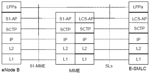
Figure 6.5.1-1 shows the protocol layering used to support transfer of LPPa PDUs between an E-SMLC and eNode B.
The LPPa protocol is transparent to the MME. The MME routes the LPPa PDUs transparently based on a short Routing ID which corresponds to the involved E-SMLC node over the S1 interface without knowledge of the involved LPPa transaction. It carries the LPPa PDUs over S1 interface either in UE associated mode or non-UE associated mode.
6.5.2 LPPa PDU Transfer for UE Positioning p. 26
Figure 6.5.2-1 shows LPPa PDU transfer between an E-SMLC and eNode B to support positioning of a particular UE.
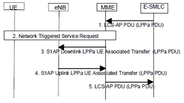
Figure 6.5.2-1: LPPa PDU Transfer between an E-SMLC and eNode B for UE Positioning
(⇒ copy of original 3GPP image)
(⇒ copy of original 3GPP image)
Step 1.
Steps 1 to 3 are triggered when the E-SMLC needs to send an LPPa message to the serving eNode B for a target UE as part of an LPPa positioning activity. The E-SMLC then sends an LCS-AP PDU (as specified in TS 29.171) to the MME including the Correlation ID corresponding to the UE and carrying an LPPa PDU comprising the message.
Step 2.
If the UE is in ECM-IDLE state (e.g. if the S1 connection was previously released due to data and signalling inactivity), the MME performs a network triggered service request as defined in TS 23.401 in order to establish a signalling connection with the UE and assign a serving eNode B.
Step 3.
The MME forwards the LPPa PDU to the serving eNode B in an S1AP Downlink UE Associated LPPa Transport message over the S1 signalling connection corresponding to the UE and includes the Routing ID related to the E-SMLC. The MME need not retain state information for this transfer - e.g. can treat any response in step 4 as a separate non-associated transfer.
Step 4.
Steps 4 and 5 are triggered when a serving eNode B needs to send an LPPa message to the E-SMLC for a target UE as part of an LPPa positioning activity. The eNode B then sends an LPPa PDU to the MME in an S1AP Uplink UE Associated LPPa Transport message and includes the Routing ID received in step 3.
Step 5.
The MME forwards the LPPa PDU to the E-SMLC associated with the Routing ID received in step 4 in an LCS-AP PDU (as specified in TS 29.171) including the Correlation ID corresponding to the UE. Steps 1 to 5 may be repeated.
6.5.3 LPPa PDU Transfer for Positioning Support p. 27
Figure 6.5.3-1 shows LPPa PDU transfer between an E-SMLC and eNodeB when related to gathering data from the eNodeB for positioning support for all UEs.
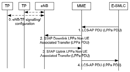
Figure 6.5.3-1: LPPa PDU Transfer between an E-SMLC and eNodeB for obtaining eNodeB Data
(⇒ copy of original 3GPP image)
(⇒ copy of original 3GPP image)
Step 0.
An eNodeB may communicate with several TPs (including PRS-only TPs in case of PRS-based TBS is supported) to configure TPs, obtain TP configuration information, etc.
Step 1.
Steps 1 and 2 are triggered when the E-SMLC needs to send an LPPa message to an eNodeB to obtain data related to the eNodeB, and possibly associated TPs. The E-SMLC determines an MME with access to the eNodeB and then sends an LCS-AP PDU (as specified in TS 29.171) to the MME carrying an LPPa PDU, the global identity of the eNodeB and the identity of the E-SMLC.
Step 2.
The MME forwards the LPPa PDU to the identified eNode B in an S1AP Downlink Non UE Associated LPPa Transport message and includes the Routing ID related to the E-SMLC. The MME need not retain state information for this transfer - e.g. can treat any response in step 3 as a separate non-associated transfer.
Step 3.
Steps 3 and 4 are triggered when an eNode B needs to send an LPPa PDU to an E-SMLC containing data applicable to the eNodeB, and possibly associated TPs. The eNodeB determines an MME with access to the E-SMLC and then sends an LPPa PDU to the MME in an S1AP Uplink Non UE Associated LPPa Transport message. The eNodeB includes the Routing ID related to the E-SMLC received at step 2.
Step 4.
The MME forwards the LPPa PDU to the E-SMLC associated to the Routing ID indicated in step 3 and includes the global identity of the eNodeB and the identity of the E-SMLC in an LCS-AP PDU (as specified in TS 29.171). Steps 1 to 4 may be repeated.
6.5.4 LPPa PDU Transfer for Assistance Information Broadcast p. 27
Figure 6.5.4-1 shows LPPa PDU transfer between an E-SMLC and eNode B to support broadcast of assistance data.
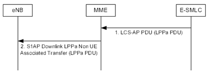
Figure 6.5.4-1: LPPa PDU Transfer between an E-SMLC and eNodeB for providing assistance information for broadcasting.
(⇒ copy of original 3GPP image)
(⇒ copy of original 3GPP image)
Step 1.
Figure 6.5.4-2 shows LPPa PDU transfer between an eNode B and E-SMLC for providing feedback to the E-SMLC on assistance data broadcasting.
Step 1 is triggered when the E-SMLC needs to send new or updated assistance information to an eNodeB for broadcasting in positioning system information messages. The E-SMLC determines an MME with access to the eNodeB and then sends an LCS-AP PDU (as specified in TS 29.171) to the MME carrying an LPPa PDU, the global identity of the eNodeB and the identity of the E-SMLC.
Step 2.
The MME forwards the LPPa PDU to the identified eNode B in an S1AP Downlink Non UE Associated LPPa Transport message and includes the Routing ID related to the E-SMLC. The MME need not retain state information for this transfer.
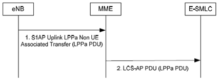
Figure 6.5.4-2: LPPa PDU Transfer between an eNodeB and E-SMLC for providing feedback on assistance data broadcasting.
(⇒ copy of original 3GPP image)
(⇒ copy of original 3GPP image)
Step 1.
Step 1 is triggered when an eNode B needs to send an LPPa PDU to an E-SMLC for providing feedback on assistance data broadcasting. Step 1 may only be triggered if the procedure in Figure 6.5.4-1 has already been performed. The eNodeB determines an MME with access to the E-SMLC and then sends an LPPa PDU to the MME in an S1AP Uplink Non UE Associated LPPa Transport message. The eNodeB includes the previously received Routing ID related to the E-SMLC (Figure 6.5.4-1).
Step 2.
The MME forwards the LPPa PDU to the E-SMLC associated to the Routing ID indicated in step 1 and includes the global identity of the eNodeB and the identity of the E-SMLC in an LCS-AP PDU (as specified in TS 29.171).
6.6 LMU-terminated protocols p. 29
6.6.1 SLm Application Protocol (SLmAP) p. 29
The SLmAP protocol, terminated between the E-SMLC and the LMU is used to support the following functions:
- delivery of target UE configuration data from the E-SMLC to the LMU
- request positioning measurements from the LMU and delivery of positioning measurements to the E-SMLC.
6.7 Signalling between an E-SMLC and LMU p. 29
6.7.1 Protocol Layering p. 29
Figure 6.7.1-1 shows the protocol layering used to support transfer of SLmAP messages between an E-SMLC and LMU.
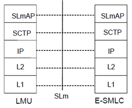
Figure 6.7.1-1: Protocol Layering for direct E-SMLC to LMU Signalling
(⇒ copy of original 3GPP image)
(⇒ copy of original 3GPP image)