Content for TS 36.305 Word version: 18.0.0
6.4 Signalling between an E-SMLC and UE p. 24
6.4.1 Protocol Layering p. 24
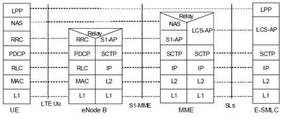
Figure 6.4.1-1 shows the protocol layering used to support transfer of LPP messages between an E-SMLC and UE. The LPP PDU is carried in NAS PDU between the MME and the UE.

6.4.2 LPP PDU Transfer p. 24
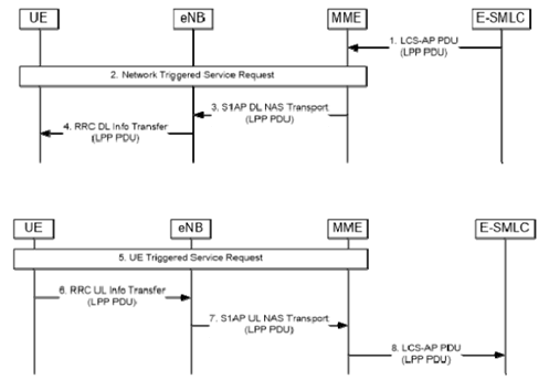
Figure 6.4.2-1 shows the transfer of an LPP PDU between an E-SMLC and UE, in the network- and UE-triggered cases. These two cases may occur separately or as parts of a single more complex operation.

Figure 6.4.2-1: LPP PDU transfer between E-SMLC and UE (network- and UE-triggered cases)
(⇒ copy of original 3GPP image)
(⇒ copy of original 3GPP image)
Step 1.
Steps 1 to 4 may occur before, after, or at the same time as steps 5 to 8. Steps 1 to 4 and steps 5 to 8 may also be repeated. Steps 1 to 4 are triggered when the E-SMLC needs to send an LPP message to the UE as part of some LPP positioning activity. The E-SMLC then sends an LCS-AP PDU to the MME carrying an LPP PDU comprising the message.
Step 2.
If the UE is in ECM-IDLE state (e.g. if the S1 connection was previously released due to data and signalling inactivity), the MME performs a network triggered service request as defined in TS 23.401 in order to establish a signalling connection with the UE and assign a serving eNode B.
Step 3.
The MME includes a session identifier (a.k.a Routing identifier defined in TS 24.171), which is associated with the positioning session between the MME and E-SMLC, and the LPP PDU in the NAS Transport Message and then forwards the NAS Transport Message to the serving eNode B in an S1AP Downlink NAS Transport message. The MME need not retain state information for this transfer; it can treat any response in step 7 as a separate non-associated transfer.
Step 4.
The eNode B forwards the NAS Transport Message to the UE in an RRC DL Information Transfer message.
Step 5.
Steps 5 to 8 are triggered when the UE needs to send an LPP PDU to the E-SMLC as part of some LPP positioning activity. If the UE is in ECM-IDLE state, the UE instigates a UE triggered service request as defined in TS 23.401 in order to establish a signalling connection with the MME and assign a serving eNode B.
Step 6.
The UE includes the session identifier (a.k.a Routing identifier defined in TS 24.171), which has been received in step 4, and an LPP PDU to the serving eNode B in an RRC UL Information Transfer message.
Step 7.
The eNode B forwards the NAS Transport Message to the MME in an S1AP Uplink NAS Transport message.
Step 8.
The MME forwards the LPP PDU to the E-SMLC in an LCS-AP PDU.