Content for TS 23.468 Word version: 18.0.0
4 Architecture Model and Concepts
4.1 General Concept
4.2 Architectural Reference Model
4.2.1 General
4.2.2 Non-roaming architecture
4.2.3 Roaming architecture
4.2.4 Architecture model using a ProSe UE-to-Network Relay for Public Safety
4.3 Reference points
4.4 High level functions
4.4.1 Unicast Delivery
4.4.2 MBMS Delivery
4.4.3 Service continuity
4.5 Network Elements
4.5.1 GCS AS
4.5.2 UE
4.5.3 PCRF
4.5.4 BM-SC
...
...
4 Architecture Model and Concepts p. 7
4.1 General Concept p. 7
This specification describes how a GCS Application Server (GCS AS) may use the enablers offered by the 3GPP system for providing a Group Communication Service (GCS). These enablers are denoted as Group Communication System Enablers (GCSE).
The GCS AS uses EPS bearer services and may use in addition MBMS bearer services for transferring application signalling and data between the GCS AS and the UEs. In uplink direction, the UE uses an EPS bearer service to exchange application signalling with the GCS AS or when it wants to send data to the GCS AS. In downlink direction the GCS AS may transfer application signalling and data via the UE individual EPS bearer services and/or via MBMS bearer service. The GCS UEs register with their GCS AS using application signalling for participating in one or multiple GCS groups.
When an MBMS bearer service is used, its broadcast service area may be pre-configured for use by the GCS AS. Alternatively, the GCS AS may dynamically decide to use an MBMS bearer service when it determines that the number of UE for a GCS group is sufficiently large within an area (e.g. within a cell or a collection of cells).
When MBMS bearer service is used, GCS AS may transfer data from different GCS groups over a single MBMS broadcast bearer. The application signalling and data transferred via MBMS bearer(s) are transparent to BM-SC and the MBMS bearer service. The GCS AS provides the UEs via GCS application signalling with all configuration information that the UE needs to receive application data via MBMS bearer services and to handle that data appropriately.
When a GCS UE moves between areas where its MBMS broadcast bearers are available or not, the UE informs the GCS AS via application signalling that it changes from MBMS broadcast bearer reception to non-reception, or vice versa, the GCS AS activates or deactivates the downlink application signalling and data transfer via the UE individual EPS bearer(s) as appropriate. To accomplish service continuity, a UE may temporarily receive the same GCS application signalling and data in parallel via EPS bearer(s) and MBMS service(s). The GCS UE application discards any received application signalling or data duplicates.
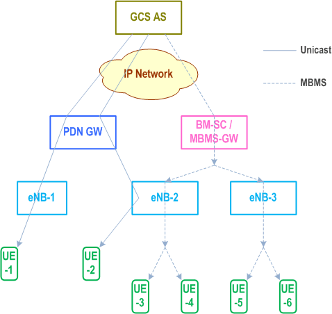
The following diagram shows an example of a scenario where a combination of Unicast and MBMS Delivery is used for a particular media, belonging to a single group, by the GCS AS on the DL to different UEs. Here, UE-1 and UE-2 receive DL traffic over unicast whereas UEs 3-6 receive DL traffic over MBMS.

4.2 Architectural Reference Model p. 9
4.2.1 General p. 9
This model assumes that the GCS AS is not associated with any PLMN (regardless of the subscription of the UEs that use it). The GCS AS is merely perceived as a third party application server by each serving PLMN. In addition:
- When the group communication service is provided using Unicast Delivery, there are no additional requirements in order to provide GCS in roaming other than enabling normal EPS roaming and the ability of the GCS AS to access QoS control capabilities via Rx interface in the HPLMN (for the non-roaming case and the roaming Home routed case). For the Local breakout scenario, QoS control may be established via hPCRF and the S9 interface towards the vPCRF directly to the vPCRF as specified in TS 23.203. The GCS AS shall provide information to enable session binding as defined in clause 6.1.1.2 of TS 23.203.
- When MBMS Delivery to particular regions of the serving PLMN is required, the GCS AS needs to have access to an MB2 interface offered by the serving PLMN.
4.2.2 Non-roaming architecture p. 10
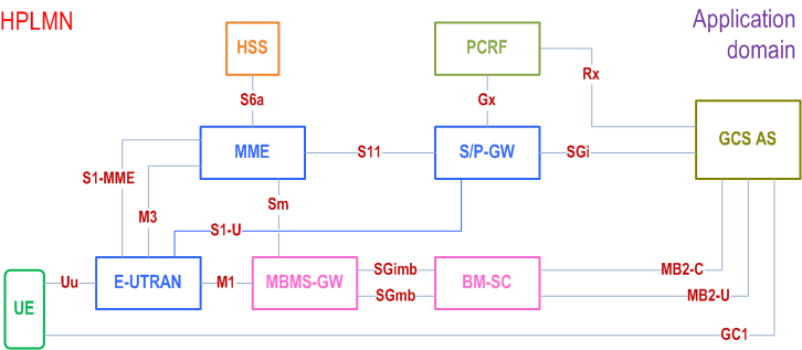
Figure 4.2.2-1 shows a high level view of the architecture for the non-roaming scenario.

4.2.3 Roaming architecture p. 10
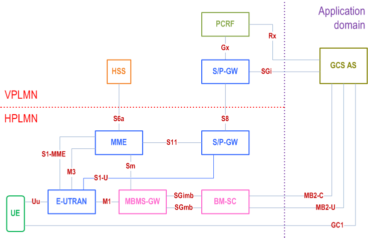
Figure 4.2.3-1 shows a high level view of the architecture applicable for the Home routed roaming model for Unicast Delivery. For MBMS Delivery, BM-SC in the V-PLMN has a direct MB2 connection with the GCS AS.

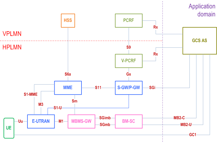
Figure 4.2.3-2 shows a high level view of the architecture applicable for the Local Breakout roaming model for Unicast Delivery. For MBMS Delivery, BM-SC in the V-PLMN has a direct MB2 connection with the GCS AS.

The GCS AS is configured with mapping information which contains an IP address range and the corresponding PLMN which is responsible for this IP address range {(IPx..IPy) → PLMN ID}.
In roaming scenarios, the GCS AS receives the UE IP address, the HPLMN ID and the VPLMN ID via GC1 signalling from the UE. If the configured PLMN entry corresponding to the UE's IP address matches the HPLMN ID sent by the UE, the GCS AS selects a PCRF from the UE's HPLMN (hPCRF) using the procedures defined in TS 23.203. Otherwise, the GCS AS may select a PCRF from either the HPLMN or the VPLMN using the procedures defined in TS 23.203. The GCS AS makes this selection based on agreements with HPLMN/VPLMN operators.
4.2.4 Architecture model using a ProSe UE-to-Network Relay for Public Safety |R13| p. 12
A Group Communication Service (GCS) is supported to the Remote UE using the ProSe UE-to-Network Relay through the PC5 reference point specified in TS 23.303. In Figure 4.2.4-1, the architecture includes this scenario. This architecture is only applied when using a Group Communication Service Application Server (GCS AS) for public safety.

4.3 Reference points p. 12
4.3.1 General p. 12
The reference points used to support group communications are listed in the following clauses.
4.3.2 List of Reference Points p. 12
4.3.2.1 GC1 reference point p. 12
The GC1 reference point exists between the GCS AS and the application client on the UE, and is not specified in this release of this specification. However, this specification includes high level descriptions of interactions on the GC1 reference point, which are necessary in order to convey certain information (e.g. PLMN ID) and perform certain functions (e.g. register or re-register with serving PLMN ID) in order for the EPS and MBMS bearer services to be delivered accurately. Some of these aspects are specified in clause 4.2.1, clause 4.4.1, clause 4.4.2, clause 4.5.1, clause 4.5.2, clause 5.3.2 and clause 5.3.3 of this specification.
4.3.2.2 MB2 reference point p. 12
The MB2 reference point exists between the GCS AS and the BM-SC.
The MB2 reference point provides the ability for the application to:
- Request the allocation/deallocation of a set of TMGIs,
-
Request to activate, deactivate, and modify an MBMS bearer:
- this may include request related to BM-SC applying FEC or RoHC or both to a set of media.
- Notify the application of the status of an MBMS bearer.
4.3.2.3 SGmb/SGi-mb/M1/M3 reference points p. 13
The SGmb/SGi-mb/M1/M3 reference points are internal to the MBMS system and are defined in TS 23.246.
4.3.2.4 Rx reference point p. 13
The Rx reference point is defined in TS 29.214. The GCS AS uses the Rx interface to manage unicast resources.
4.4 High level functions p. 13
4.4.1 Unicast Delivery p. 13
The UE and GCS AS use the EPS bearers defined in TS 23.401 for Unicast Delivery. The EPS bearers are used for the following:
- Exchanging GC1 signalling between UE and GCS AS.
- Transport of data on the uplink from UE to the GCS AS.
- Transport of data on the downlink from GCS AS to UE when MBMS Delivery is not desirable or possible.
4.4.2 MBMS Delivery p. 13
The GCS AS uses the MBMS bearers defined in TS 23.246 for MBMS Delivery. The MBMS bearer is used to transport data on the downlink from the GCS AS to the UE. The MBMS bearer(s) used for MBMS Delivery can be pre-established before the group communication session is setup or can be dynamically established after the group communication session is setup.
4.4.3 Service continuity p. 13
The UE uses the service continuity procedures defined in clause 5.3 for switching between Unicast Delivery and MBMS Delivery.
4.5 Network Elements p. 13
4.5.1 GCS AS p. 13
The GCS AS shall support the following functionality:
- Exchanging GC1 signalling (including GCS session and group management aspects) with the UE.
- Receiving uplink data from the UE over unicast
- Delivery of data to all the UEs belonging to a group using Unicast Delivery and/or MBMS Delivery.
- Transport of application level session information via Rx interface towards PCRF.
- Support for service continuity procedures for a UE to switch between Unicast Delivery and MBMS Delivery as specified in clause 5.3.
4.5.2 UE p. 14
The GCS capable UE shall support the following functionality:
- Exchanging GC1 signalling (including GCS session and group management aspects) with the GCS AS.
- Provision of a UE specific IDLE MODE DRX cycle length to the core network as specified in clause 5.13 of TS 23.401.
- Receiving data from a GCS AS using either Unicast Delivery or MBMS Delivery, or both simultaneously.
- Sending data on the uplink to the GCS AS using unicast.
- Support for service continuity procedures to switch between Unicast Delivery and MBMS Delivery as specified in clause 5.3.
- Simultaneous monitoring and reception of one or more MBMS bearer(s).
4.5.3 PCRF p. 14
The PCRF supports the functionality defined in TS 23.203.
4.5.4 BM-SC p. 14
The BM-SC shall support the following functionality:
- MBMS Broadcast Mode procedures defined in TS 23.246.
- MB2 procedures defined in clause 5.1 for activating, deactivating and modifying an MBMS bearer.