Content for TS 23.468 Word version: 18.0.0
5 Functional Description and Information Flow
5.1 MB2: Interface between GCS AS and BM-SC
5.1.1 General
5.1.2 MB2 Procedures
5.1.2.1 General
5.1.2.2 TMGI Management
5.1.2.3 Activating and Deactivating an MBMS bearer
5.1.2.4 Modify MBMS Bearer Procedure
5.1.2.5 MBMS Delivery Status Indication Procedure
5.2 Specific Usage of EPS Bearers for GCS
...
...
5 Functional Description and Information Flow p. 14
5.1 MB2: Interface between GCS AS and BM-SC p. 14
5.1.1 General p. 14
MB2 offers access to the MBMS bearer service from a GCS AS. MB2 carries control plane signalling (MB2-C) and user plane (MB2-U) between GCS AS and BM-SC. MB2 has the following properties:
- MB2 is used by the GCS AS to interact with the BM-SC for MBMS bearer management.
- The GCS AS may use the MBMS service from multiple BM-SCs, each with a separate MB2 interface.
- The BM-SC shall provide service to multiple GCS ASs via a separate MB2 interface.
- Within one PLMN, an MBMS session is supported by exactly one BM-SC and provided for only one GCS AS.
- The data transferred via MBMS bearer(s) by the GCS AS is transparent to the BM-SC. A GCS AS may transfer data from one or multiple GCS groups via a single MBMS bearer.
- MB2 is a standardized secured interface to an AS.
- The GCS AS needs to be configured with the IP addresses or a FQDN of the contact points of MB2-C. The MB2-C contact points need to be configured per PLMN ID.
- The user plane transport information (e.g. IP address/UDP port) for delivering group communication data flow from the GCS AS to the BM-SC over MB2-U shall be exchanged over MB2-C.
5.1.2 MB2 Procedures p. 15
5.1.2.1 General p. 15
The MB2 interface provides the ability for the application to use the functionality of the MBMS system to deliver data to group members over MBMS. The procedures supported include:
- allocation of a set of TMGIs (TS 23.246) by the BM-SC at the request of the GCS AS, (see clause 5.1.2.2.2),
- deallocation of a set of TMGIs by the BM-SC at the request of the GCS AS, (see clause 5.1.2.2.3),
-
activating an MBMS bearer, (see clause 5.1.2.3.2):
- this may include request related to BM-SC applying FEC or RoHC or both to a set of media.
- deactivating an active MBMS bearer, (see clause 5.1.2.3.3),
- modifying characteristics of an active MBMS bearer, (see clause 5.1.2.4), and
- reporting of MBMS delivery status from the BM-SC to the GCS AS, (see clause 5.1.2.5).
5.1.2.2 TMGI Management p. 15
5.1.2.2.1 General p. 15
TMGIs are managed between the GCS AS and the BM-SC using the following explicit allocation and deallocation procedures upon request from the GCS AS.
TMGIs may also be allocated automatically by the BM-SC at bearer activation as described in clause 5.1.2.3.2.
Each TMGI is allocated by the BM-SC for a given period of time determined by the BM-SC. If the GCS AS wants to retain access to a TMGI for an extended period of time the GCS AS needs to request extension of the allocation period. The GCS AS may request an extension of the allocation period at any time prior to expiry of the time period. The actions consequent upon expiry of a TMGI allocation period are described in clause 5.1.2.2.4.
5.1.2.2.2 TMGI Allocation Procedure p. 15
The TMGI Allocation procedure is used by the GCS AS to request a set of TMGIs. This procedure may also be used to renew the expiration time for already allocated TMGIs.
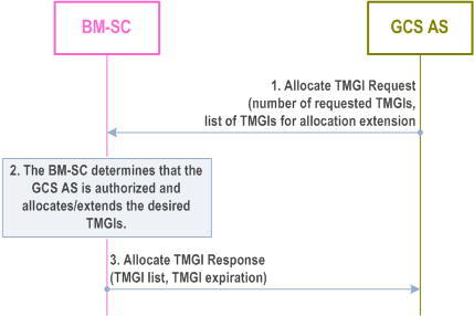
Figure 5.1.2.2.1-1 provides the procedure used between the GCS AS and the BM-SC to allocate a set of TMGIs to the GCS AS.
Step 1.
When the GCS AS wishes to have the BM-SC allocate one or more TMGIs to it, the GCS AS sends an Allocate TMGI Request message to the BM-SC, including the number of requested TMGIs. The GCS AS may include a list of TMGIs that are already allocated to the GCS AS, and for which the GCS AS wishes to obtain a later expiration time. The number of TMGIs requested may be zero, if this procedure is used only to renew the expiration time for already allocated TMGIs.
Step 2.
The BM-SC shall determine whether the GCS AS is authorized to receive the TMGIs and allocates a set of TMGIs. The BM-SC determines an expiration time for the TMGIs. If a list of TMGIs has been received in the Allocate TMGI Request message, the BM-SC also determines whether the TMGIs are allocated to the requesting GCS AS and if yes, whether the expiration time for those TMGIs can be set to the new expiration time.
Step 3.
The BM-SC shall send an Allocate TMGI Response message to the GCS AS indicating the list of allocated TMGIs, and an expiration time for those TMGIs.
5.1.2.2.3 TMGI Deallocation Procedure p. 16
The TMGI Deallocation procedure is used by the GCS AS to immediately release a set of TMGIs, irrespective of their expiration times.
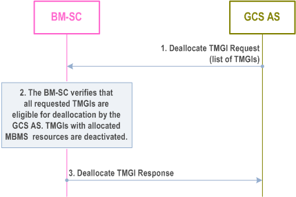
Figure 5.1.2.2.2-1 provides the procedure used between the GCS AS and the BM-SC to deallocate TMGIs.
Step 1.
When the GCS AS decides that it no longer needs one or more TMGIs that are allocated to it, the GCS AS shall send a Deallocate TMGI Request message to the BM-SC with the list of TMGIs to be deallocated. Absence of the list of TMGIs implies that all TMGIs currently allocated by the BM-SC to the GCS AS are to be deallocated.
Step 2.
The BM-SC shall determine that the GCS AS is authorized to deallocate the indicated TMGIs, and shall then deallocate the TMGIs. If MBMS resources are in use for any of the deallocated TMGIs, those resources are released using the Session Stop procedure defined in TS 23.246 and the BM-SC shall release any corresponding MB2 resources.
Step 3.
The BM-SC sends a Deallocate TMGI Response message to the GCS AS.
5.1.2.2.4 TMGI allocation period expiry p. 17
When the allocation period for a TMGI expires the TMGI and its associated Flow ID are no longer available for use by the GCS AS.
If, at the time of expiry, the TMGI is associated with a previously activated MBMS bearer (clause 5.1.2.3.2) the BM-SC shall autonomously take whatever actions are needed to stop broadcast of the MBMS bearer to the agreed MBMS service area, and shall release the MBMS resources used for the MBMS bearer using the Session Stop procedure defined in TS 23.246. The BM-SC shall send an MBMS Delivery Status Indication message to the GCS AS and shall release any corresponding MB2 resources.
At any time prior to expiry, the allocation period for a TMGI(s) may be extended as described in clause 5.1.2.2.2. A GCS AS wanting to ensure that it retains access to a TMGI should request extension of the allocation period at an adequate time before expiry, e.g. halfway through the allocation period.
5.1.2.3 Activating and Deactivating an MBMS bearer p. 17
5.1.2.3.1 General p. 17
Activating and deactivating an MBMS bearer involves the allocation/deallocation of MBMS resources, based on the MBMS bearer configuration provided by the GCS AS, using the following explicit activation and deactivation procedures upon request from the GCS AS.
MBMS bearer resources may also be deallocated autonomously by the BM-SC, upon expiry of the allocation period of the TMGI associated with the MBMS bearer, as described in clause 5.1.2.2.4.
5.1.2.3.2 Activate MBMS Bearer Procedure p. 17
The Activate MBMS Bearer procedure is used by the GCS AS to cause allocation of resources for an MBMS bearer. In addition, the GCS AS acting in the role of the Mission Critical service server as specified in TS 23.280 can request the BM-SC to apply FEC and/or RoHC to a set of medias, transported by that MBMS bearer,
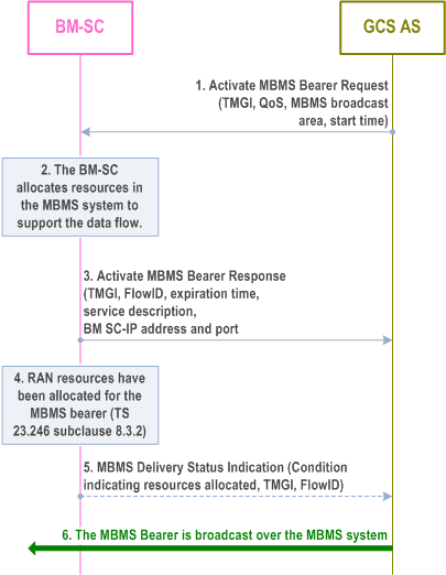
Figure 5.1.2.3.2-1 provides the procedure used between the GCS AS and the BM-SC to activate an MBMS bearer.
Step 1.
In order to activate an MBMS bearer over MB2, the GCS AS sends an Activate MBMS Bearer Request message to the BM-SC, including the TMGI which represents the MBMS bearer to be started, QoS, MBMS broadcast area, and start time. The TMGI is optional. The QoS shall be mapped into appropriate QoS parameters of the MBMS bearer. The MBMS broadcast area parameter shall include a list of MBMS Service Area Identities, or a list of cell IDs, or both.
The GCS AS may request that FEC is applied for media streams within the MBMS bearer by including for each media stream the following information elements: the SDP media descriptions (transport protocols, destination IP address and port), the identification of the FEC repair packet flow (destination IP address and port), an upper bound to the additional latency resulting to FEC application.
The GCS AS may request that RoHC is applied for IP flows within the MBMS bearer by including the following information elements: the RoHC configuration, the list of RTP and UDP flows to be header compressed, characterized by their destination IP addresses and port numbers. For each of these flows, the request may indicate a target periodicity for the full header packets.
Step 2.
If the TMGI was included, the BM-SC shall determine whether the GCS AS is authorized to use the TMGI. The BM-SC shall reject the request if the TMGI is not authorized. If the TMGI was not included in the request, the BM-SC shall assign an unused value for the TMGI. The BM-SC allocates a FlowID value corresponding to this TMGI and MBMS broadcast area. If the MBMS broadcast area parameter includes a list of cell IDs, the BM-SC may map the cell IDs into MBMS Service Area Identities subject to operator policy. The BM-SC shall then include a list of MBMS Service Area Identities and, if available, the list of cell IDs in the MBMS Session Start message. If another MBMS bearer with the same TMGI is already activated, the BM-SC shall accept the request only if the MBMS broadcast area in the new request is not partly or completely overlapping with any existing MBMS bearer(s) using the same TMGI as according to TS 23.246 and shall allocate a unique FlowID for the newly requested MBMS bearer. The BM-SC shall allocate MBMS resources to support content delivery of the MBMS bearer to the requested MBMS broadcast area using the Session Start procedure defined in TS 23.246. If the GCS AS requested that FEC and/or RoHC are applied, the BM-SC shall allocate resources to apply FEC and/or RoHC as requested.
Step 3.
The BM-SC shall send an Activate MBMS Bearer Response message to the GCS AS, including the TMGI, the allocated FlowID, service description, BM-SC IP address and port number for the user-plane, and an expiration time. The service description contains MBMS bearer related configuration information as defined in TS 26.346 (e.g. radio frequency and MBMS Service Area Identities). If the BM-SC mapped the cell IDs into the MBMS Service Area Identities in Step 2, then the service description shall contain the MBMS Service Area Identities that the BM-SC included in the MBMS Session Start message. The expiration time is included only if the BM-SC has allocated a TMGI as a result of this procedure.
Step 4.
The BM-SC receives an MBMS session response message from the MBMS GW and is notified that the MBMS bearer is activated in RAN. See clause 8.3.2 of TS 23.246.
Step 5.
The BM-SC may send a MBMS Delivery Status Indication message to the GCS AS, including the TMGI and optionally the allocated FlowID and radio resource allocation condition.
5.1.2.3.3 Deactivate MBMS Bearer Procedure p. 19
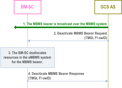
The Deactivate MBMS Bearer procedure is used by the GCS AS to cause deallocation of resources for an MBMS bearer.
Step 1.
The MBMS bearer is being broadcast over the MBMS system.
Step 2.
When the GCS AS determines that the MBMS bearer is no longer needed, it shall send a Deactivate MBMS Bearer Request message to the BM-SC, including the TMGI and FlowID representing the MBMS bearer to be deactivated.
Step 3.
The BM-SC shall determine whether the GCS AS is authorized to use the TMGI and shall take whatever actions are needed to stop broadcast of the MBMS bearer to the agreed MBMS service area, and to deallocate MBMS resources used for the MBMS bearer using the Session Stop procedure defined in TS 23.246.
Step 4.
The BM-SC shall send a Deactivate MBMS Bearer Response message to the application, including the TMGI, the FlowID, and a result.
5.1.2.4 Modify MBMS Bearer Procedure p. 20
The Modify MBMS Bearer procedure is used by the GCS AS to cause modification of the priority and preemption values for an MBMS bearer, the MBMS broadcast area, or both. In addition, the GCS AS acting in the role of the Mission Critical service server as specified in TS 23.280 can request the BM-SC to apply FEC and/or RoHC to a set of medias, transported by that MBMS bearer.
Figure 5.1.2.4-1 provides a description of the procedure used between the GCS AS and the BM-SC to modify an activated MBMS bearer.
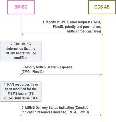
Step 1.
When the GCS AS determines that an activated MBMS bearer needs to be modified, it shall send a Modify MBMS Bearer Request message to the BM-SC, including the TMGI, FlowID, any new priority and preemption characteristics to be used, and the MBMS broadcast area. The priority and preemption characteristics and the MBMS broadcast area are optional parameters but one of them needs to be included in the Modify MBMS Bearer request. The MBMS broadcast area parameter shall include a list of MBMS Service Area Identities, or a list of cell IDs, or both.
The GCS AS may request that FEC is applied for media streams within the MBMS bearer by including for each media stream the following information elements: the SDP media descriptions (transport protocols, destination IP address and port), the identification of the FEC repair packet flow (destination IP address and port), an upper bound to the additional latency resulting to FEC application.
The GCS AS may request that RoHC is applied for IP flows within the MBMS bearer by including the following information elements: The RoHC configuration, the list of RTP and UDP flows to be header compressed, characterized by their destination IP address and port numbers. For each of these flows, the request may indicate a target periodicity for the full header packets.
Step 2.
If the MBMS broadcast area is being modified, the BM-SC shall accept the request only if the new MBMS broadcast area is not partly or completely overlapping with the MBMS broadcast area of any other existing MBMS bearer(s) with the same TMGI, in accordance with TS 23.246. The BM-SC shall modify the characteristics of the MBMS bearer using the Session Update procedure defined in TS 23.246. If the MBMS broadcast area parameter is present and includes a list of cell IDs, the BM-SC may map the cell IDs into MBMS Service Area Identities subject to operator policy. The BM-SC shall then include a list of MBMS Service Area Identities and, if available, the list of cell IDs in the MBMS Session Update message.
Step 3.
The BM-SC shall send a Modify MBMS Bearer Response message to the GCS AS, including the TMGI, FlowID, and the result. If the BM-SC mapped the cell IDs into the MBMS Service Area Identities in Step 2, then the service description shall contain the MBMS Service Area Identities that the BM-SC included in the MBMS Session Update message.
Step 4.
The BM-SC receives an MBMS Session Update Response message from the MBMS GW and is notified that the MBMS bearer is modified in RAN. See TS 23.246 clause 8.8.4.
Step 5.
The BM-SC may send a MBMS Delivery Status Indication message to the GCS AS, including the TMGI and optionally the allocated FlowID and radio resource allocation condition.
If the GCS AS requested that FEC is applied, the BM-SC shall include an indication of success or failure for each media stream where FEC was requested to be applied.
If the GCS AS requested that RoHC is applied, the BM-SC shall include an indication of success or failure for each IP flow where RoHC was requested to be applied.
5.1.2.5 MBMS Delivery Status Indication Procedure p. 21
The MB2 interface allows the BM-SC to notify the GCS AS of conditions affecting the delivery of services that use MBMS Delivery. The occurrence of the indicated condition may have been detected at the BM-SC or may have been reported to the BM-SC by other entities involved in the MBMS delivery.
The BM-SC sends the MBMS Delivery Status Indication message which includes an identification of the condition whose occurrence triggered the sending of the message and may include other information.
Figure 5.1.2.5-1 illustrates the MBMS Delivery Status Indication procedure.

5.2 Specific Usage of EPS Bearers for GCS p. 21
Each UE participating in the Group Communication Service uses one or multiple EPS bearers for exchanging application signalling and data with the GCS AS. The EPS bearer services are specified in TS 23.401 and TS 23.203.
In order to enable GCS, a PDN connection needs to be established that can be used for GC1 signalling exchange. When the PDN connection gets established the PCC functionality determines a QCI and an ARP for the default bearer, which may be used for GC1 signalling. Alternatively, during PDN connection establishment a dedicated bearer may be established for GC1 signalling by configuring PCC rules accordingly.
A GCS UE may join multiple GCS groups, which are served by one or more EPS bearers. The GCS AS determines the service characteristics of a specific Group Communication Service, e.g. media or flow description and priority, which is used by the PCRF to determine the EPS bearer configuration appropriate for GCS. The GCS AS updates the PCRF with service characteristics to initiate any required update of the EPS bearer configuration, e.g. when the UE joins or leaves a GCS group or when a GCS data exchange starts or stops.
Whenever the UE's bearer configuration needs to be updated, the GCS AS provides the updated or new service characteristics to the PCRF. From service characteristics PCRF determines the required bearer configuration, including QCI and ARP, and requests the PCEF amendment of the UE's EPS bearers accordingly. If the priority of the application Group Communication session changes, the GCS AS provides an update of the service characteristics towards the PCRF via the Rx interface. The PCRF translates the service characteristics to PCC policies and forwards its policy decision to the PCEF. The PCEF determines, based on policies provided by the PCRF, whether the PCEF modifies already established bearers or whether the PCEF establishes dedicated bearer(s) with the determined bearer characteristics.
The PCRF is not aware of the GCS group(s).
To obtain the responsiveness desired for GCS the GCS UE shall signal the Idle Mode DRX value to the MME, using the procedures described in TS 23.401. The E-UTRAN derives from the QCI the configuration for delivering an equivalent responsiveness in Connected Mode. When performing the S1 interface paging procedure for a DownlinkData Notification for a bearer associated with either QCI 65 or QCI 69 (e.g. Mission Critical Push To Talk), the Paging Priority IE needs to be set to a value such that the E-UTRAN can correctly prioritize the contents of its radio interface paging messages to enable low latency for the first downlink packet on that bearer. To enable the MME to send this Paging Priority IE on the S1 interface, the bearer(s) associated with QCI 65 and QCI 69 should have appropriate ARP(s).