Content for TS 23.283 Word version: 19.1.0
1…
10…
10.2…
10.3…
10.3.2
10.3.3…
10.3.4…
10.3.5…
10.3.6…
10.3.7…
10.3.8…
10.4…
10.5…
10.6…
10.6.2…
10.6.3…
10.7…
10.8…
10.11…
10.12…
10.14…
10.15…
10.17…
10.5 Floor control
10.5.1 General
10.5.2 Information flows for floor control
10.5.3 Interworking floor control
10.5.4 Floor override without using floor revoked on an interworking group
10.5.5 Floor control on an interworking group homed in the LMR system
10.5.6 Floor control on an interworking group homed in the MCPTT system
10.5.7 Floor control without local filtering on an interworking group defined in the LMR system
10.5.8 Floor control without local filtering on an interworking group defined in the MCPTT system
10.5.9 Floor control in private call controlled by the LMR system
10.5.10 Floor control in private call controlled by the MCPTT system
...
...
10.5 Floor control p. 103
10.5.1 General p. 103
Floor control for interworking applies to both private call and group call.
Floor control involving a single MCPTT server is described in TS 23.379. Floor control involving multiple MCPTT servers is also described in TS 23.379 in that a primary MCPTT server is interconnected to a partner MCPTT server. Subclause 10.5.2 describes information flows for floor control between an MCPTT server and an IWF, and are based on those defined interconnection in TS 23.379. Subclause 10.5.3 describes aspects of floor control that apply to interworking groups and interworking private calls. Subclauses 10.5.4 / 10.5.6 and 10.5.5 / 10.5.7 describe general cases of floor control on an interworking group defined in the LMR system and in the MCPTT system respectively, where the partner system has been configured to apply/not apply local filtering of floor control requests before communicating with the primary system. Subclauses 10.5.9 and 10.5.10 describe general cases of floor control in a private call, where the controlling role is taken by the LMR system and the MCPTT system respectively.
10.5.2 Information flows for floor control p. 103
10.5.2.1 General p. 103
The following sections describe information flows for interworking floor control.
In the following information flows the MCPTT ID and its associated functional alias represents the LMR user, the IWF, or the MCPTT user depending on the interworking methods being used and the message source/destination.
10.5.2.2 IWF floor request p. 103
Table 10.5.2.2-1 describes the information flow IWF floor request, from the IWF to the MCPTT floor control server and from the MCPTT floor control server to the IWF, which is used to request the floor for media transfer.
| Information element | Status | Description |
|---|---|---|
| MCPTT ID | M | Requester identity |
| Functional alias | O | Functional alias of the requester |
| Floor priority | M | Priority of the request |
| Source identifier | O | Identifies the communication, e.g. by identifying the media flow within a media multiplex, present only if media multiplexing |
| Location | O | Location information of requester |
10.5.2.3 IWF floor granted p. 103
Table 10.5.2.3-1 describes the information flow IWF floor granted, from the IWF to the MCPTT floor control server and from the MCPTT floor control server to the IWF, which is used to indicate that a request for floor is granted and media transfer is possible.
| Information element | Status | Description |
|---|---|---|
| MCPTT ID | M | Granted party identity |
| Functional alias | O | Functional alias of the granted party identity |
| Duration | M | The time for which the granted party is allowed to transmit |
| Source identifier | O | Identifies the communication, e.g. by identifying the media flow within a media multiplex, present only if media multiplexing |
| Acknowledgement required | O | Indicates if acknowledgement from the floor participant is required |
10.5.2.4 IWF floor rejected p. 104
Table 10.5.2.4-1 describes the information flow IWF floor rejected, from the IWF to the MCPTT floor control server and from the MCPTT floor control server to the IWF, which is used to indicate that a request for the floor is rejected.
| Information element | Status | Description |
|---|---|---|
| MCPTT ID | M | Rejected party identity |
| Functional alias | O | Functional alias of the rejected party |
| Source identifier | O | Identifies the communication, e.g. by identifying the media flow within a media multiplex, present only if media multiplexing |
| Rejection cause | O | Indicates the cause for floor rejection |
| Acknowledgement required | O | Indicates if acknowledgement from the floor participant is required |
10.5.2.5 IWF floor request cancel p. 104
Table 10.5.2.5-1 describes the information flow IWF floor request cancel, from the IWF to the MCPTT floor control server and from the MCPTT floor control server to the IWF, which is used to request cancelling the floor request from the floor request queue.
| Information element | Status | Description |
|---|---|---|
| MCPTT ID | M | Identity for the requester |
| Functional alias | O | Functional alias of the requester |
| List of MCPTT IDs | M | Target identity (Identities) whose floor request is to be cancelled |
| Source identifier | O | Identifies the communication, e.g. by identifying the media flow within a media multiplex, present only if media multiplexing |
10.5.2.6 IWF floor request cancel response p. 104
Table 10.5.2.6-1 describes the information flow IWF floor request cancel response, from the IWF to the MCPTT floor control server and from the MCPTT floor control server to the IWF, which is used to indicate the response for the floor request cancellation.
| Information element | Status | Description |
|---|---|---|
| MCPTT ID | M | Identity of party that initiated the cancellation request |
| Functional alias | O | Functional alias of the requester |
| Source identifier | O | Identifies the communication, e.g. by identifying the media flow within a media multiplex, present only if media multiplexing |
| Acknowledgement required | O | Indicates if acknowledgement from the floor participant is required |
10.5.2.7 IWF floor request cancel notify p. 104
Table 10.5.2.7-1 describes the information flow IWF floor request cancel notify, from the IWF to the MCPTT floor control server and from the MCPTT floor control server to the IWF, which is used to indicate the floor request is cancelled by the administrator/floor control server.
| Information element | Status | Description |
|---|---|---|
| MCPTT ID | M | Identity of the administrator |
| Functional alias | O | Functional alias of the administrator |
| Source identifier | O | Identifies the communication, e.g. by identifying the media flow within a media multiplex, present only if media multiplexing |
| Acknowledgement required | O | Indicates if acknowledgement from the floor participant is required |
10.5.2.8 IWF floor idle p. 105
Table 10.5.2.8-1 describes the information flow IWF floor idle, from the IWF to the MCPTT floor control server and from the MCPTT floor control server to the IWF, which is used to indicate that a session is in idle status, i.e. the floor is not granted to any party.
| Information element | Status | Description |
|---|---|---|
| Source identifier | O | Identifies the communication, e.g. by identifying the media flow within a media multiplex, present only if media multiplexing |
| Acknowledgement required | O | Indicates if acknowledgement from the floor participant is required |
10.5.2.9 IWF floor release p. 105
Table 10.5.2.9-1 describes the information flow IWF floor release, from the IWF to the MCPTT floor control server and from the MCPTT floor control server to the IWF, which is used to indicate the media transfer is completed and the floor is released.
| Information element | Status | Description |
|---|---|---|
| MCPTT ID | M | Identity of party that released the floor |
| Functional alias | O | Functional alias of the party that released the floor |
| Source identifier | O | Identifies the communication, e.g. by identifying the media flow within a media multiplex, present only if media multiplexing |
10.5.2.10 IWF floor taken p. 105
Table 10.5.2.10-1 describes the information flow IWF floor taken, from the IWF to the MCPTT floor control server and from the MCPTT floor control server to the IWF, which is used to indicate the floor is granted to another MCPTT user.
| Information element | Status | Description |
|---|---|---|
| MCPTT ID | M | Identity for the granted party |
| Functional alias | O | Functional alias for the granted party |
| Source identifier | O | Identifies the communication, e.g. by identifying the media flow within a media multiplex, present only if media multiplexing |
| Permission to request the floor | O | Indicates whether receiving parties are allowed to request the floor or not (e.g. broadcast call). |
| Acknowledgement required | O | Indicates if acknowledgement from the floor participant is required |
| Location | O | Location information of the granted party |
10.5.2.11 IWF floor revoked p. 106
Table 10.5.2.11-1 describes the information flow IWF floor revoked, from the IWF to the MCPTT floor control server and from the MCPTT floor control server to the IWF, which is used to indicate the floor is revoked from its current holder (the floor participant who was granted the floor).
| Information element | Status | Description |
|---|---|---|
| MCPTT ID | M | Revoked party identity |
| Functional alias | O | Functional alias of the revoked party |
| Source identifier | O | Identifies the communication, e.g. by identifying the media flow within a media multiplex, present only if media multiplexing |
| Acknowledgement required | O | Indicates if acknowledgement from the floor participant is required |
10.5.2.12 IWF floor acknowledgement p. 106
Table 10.5.2.12-1 describes the information flow IWF floor acknowledgement, from the IWF to the MCPTT floor control server and from the MCPTT floor control server to the IWF, which is used to provide an acknowledgement if the acknowledgement is required in the received floor control message.
| Information element | Status | Description |
|---|---|---|
| MCPTT ID | M | Identity of the sender. |
| Functional alias | O | Functional alias of the sender |
10.5.2.13 IWF queue position request p. 106
Table 10.5.2.13-1 describes the information flow IWF queue position request, from the IWF to the MCPTT floor control server and from the MCPTT floor control server to the IWF, which is used to request the position in the floor request queue. The MCPTT server and the MCPTT client that support queuing of the floor control requests shall support this information flow.
| Information element | Status | Description |
|---|---|---|
| MCPTT ID | M | Identity of party whose floor position is requested |
| Functional alias | O | Functional alias of the party whose floor position is requested |
| Source identifier | O | Identifies the communication, e.g. by identifying the media flow within a media multiplex, present only if media multiplexing |
10.5.2.14 IWF queue position info p. 106
Table 10.5.2.14-1 describes the information flow IWF queue position info, from the IWF to the MCPTT floor control server and from the MCPTT floor control server to the IWF, which is used to indicate the floor request is queued and the queue position to the floor requesting UE.
| Information element | Status | Description |
|---|---|---|
| MCPTT ID | M | Identity of party whose floor position is provided |
| Functional alias | O | Functional alias of the party whose floor position is provided |
| Queue position info | M | Position of the queued floor request in the queue |
| Source identifier | O | Identifies the communication, e.g. by identifying the media flow within a media multiplex, present only if media multiplexing |
| Acknowledgement required | O | Indicates if acknowledgement from the floor participant is required |
10.5.2.15 IWF unicast media stop request p. 107
Table 10.5.2.15-1 describes the information flow IWF unicast media stop request, from the IWF to the MCPTT floor control server and from the MCPTT floor control server to the IWF, which is used to indicate that the unicast media flow of the designated communication does not need to be sent to the client indicated by the MCPTT ID.
| Information element | Status | Description |
|---|---|---|
| MCPTT ID | M | Identity of the requester |
| Functional alias | O | Functional alias of the requester |
| Source identifier | O | Identifies the communication whose media flow is to be stopped, e.g. by identifying the media flow within a media multiplex, present only if media multiplexing |
10.5.2.16 IWF unicast media resume request p. 107
Table 10.5.2.16-1 describes the information flow IWF unicast media resume request, from the IWF to the MCPTT floor control server and from the MCPTT floor control server to the IWF, which is used by the floor control server to request that the unicast media flow of the designated communication is to be sent to the client indicated by the MCPTT ID.
| Information element | Status | Description |
|---|---|---|
| MCPTT ID | M | Identity of the requester |
| Functional alias | O | Functional alias of the requester |
| Source identifier | O | Identifies the communication whose media flow is to be resumed, e.g. by identifying the media flow within a media multiplex, present only if media multiplexing |
10.5.2.17 IWF floor talker ID update |R16| p. 107
Table 10.5.2.17-1 describes the information flow IWF floor talker ID update, from the IWF to the MCPTT floor control server and from the MCPTT floor control server to the IWF, which is used to indicate that the talker ID has changed for the current MCPTT user granted the floor.
| Information element | Status | Description |
|---|---|---|
| MCPTT ID | M | Identity for the party using the floor |
| Functional alias | O | Functional alias associated with the MCPTT ID using the floor |
| Source identifier | O | Identifies the communication, e.g. by identifying the media flow within a media multiplex, present only if media multiplexing |
10.5.3 Interworking floor control p. 108
Subclause 10.9.1.4.1 of TS 23.379 describes floor control involving groups in multiple MCPTT systems where floor control arbitration resides with the primary MCPTT server and all floor control messages are routed to that primary MCPTT server. The group is homed on the primary MCPTT server.
An interworking group can be homed on the MCPTT server or on the LMR system. When the group is homed on the MCPTT server the floor control server is on this MCPTT server. When the group is homed on the LMR system the floor control server is represented by the IWF.
The primary MCPTT system of an MCPTT group is defined by configuration and identified by the MC service group ID.
Subclause 10.9.1.4.2 of TS 23.379 describes floor control involving groups in multiple MCPTT systems where the partner MCPTT system filters its MCPTT users' floor requests before communicating with the floor control server of the primary MCPTT system. When an MCPTT system is interworking with an IWF, depending on where the group is homed the MCPTT server, or the IWF can filter floor control requests in the same way as an interconnected MCPTT system.
In a private call, one of the IWF or MCPTT server acts as the controlling floor control server within the call, and manages arbitration of floor control requests received from both users in the call. The entity (MCPTT server or IWF) that does not fulfil the controlling role shall send all floor control requests from its served call participant to the controlling floor control server without filtering.
10.5.4 Floor override without using floor revoked on an interworking group p. 108
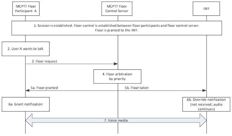
This procedure describes the case where a transmitting radio cannot be signalled that the floor has been taken or revoked. Within the context of interworking between MCPTT and LMR systems, this condition can occur due to both MCPTT and LMR users obtaining the floor simultaneously, or the floor granted to an LMR user is taken by an MCPTT user.
Figure 10.5.4-1 shows the high-level procedure where an MCPTT session is already established between the floor participants (with floor granted to an LMR user represented by the IWF) and the floor control server (with an override based on priority and configured to permit the transmission of overridden floor participant from the IWF). The group is defined in the MCPTT system and the MCPTT Server is the floor control server. Only two UEs involved in the session are shown for simplicity.
Pre-conditions:
- The MCPTT floor control server has been configured to support override.
- The override supported in this case permits both the overridden floor participant and the overriding floor participant to be transmitting.
- An MCPTT session is established between an MCPTT client, the interworked system, and MCPTT server.
- Session is ongoing.
Step 1.
It is assumed that the floor participant B (represented by the IWF in Figure 10.5.4-1) has been given the floor and is transmitting voice media.
Step 2.
Floor participant A, having a floor priority which is relatively higher than that of floor participant B, wants to send voice media over the session.
Step 3.
Floor participant A sends a floor request message to the floor control server.
Step 4.
The floor control server determines to accept the floor request from floor participant A based on arbitration result e.g., according to the floor priority information that is received in the floor request message.
Step 5a.
Floor control server responds with a floor granted message to floor participant A.
Step 5b.
Floor control server sends a floor taken message to the other floor participants (via the IWF). Floor participant B continues transmitting the (overridden) voice media transmission.
Step 6a.
The floor granted causes the user of floor participant A to be notified.
Step 6b.
Floor participant B cannot be notified of the status because it is unable to receive the message and continues transmitting.
Step 7.
Floor participant A (overriding) starts sending voice media over the session established beforehand.
10.5.5 Floor control on an interworking group homed in the LMR system p. 110
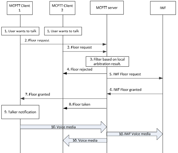
Figure 10.5.5-1 shows the procedure for floor control on an interworking group homed in the LMR system. Simultaneous floor requests are included to show various aspects of interworking floor control.
Pre-conditions:
- The interworking group is homed in the LMR system.
- The MCPTT server is configured to locally filter competing floor control requests before communicating with the IWF.
- MCPTT client 1, MCPTT client 2, and LMR users (represented by the IWF) are affiliated to that group.
- An interworking group call is ongoing involving MCPTT users and LMR users (represented by the IWF). The floor is currently idle.
Step 1.
The users of MCPTT Client 1 and MCPTT Client 2 both want to send voice media over the session.
Step 2.
MCPTT Clients 1 and 2 send floor request messages to the floor control server.
Step 3.
The MCPTT floor control server determines to accept the floor request from MCPTT Client 1 based on local arbitration results (e.g., according to priority information versus the competing request from MCPTT client 2).
Step 4.
The user of MCPTT client 2 is notified that their floor request was rejected.
Step 5.
Since the group is homed in the LMR system the MCPTT floor control server forwards the floor request to the IWF for final floor control determination. The IWF performs floor arbitration in conjunction with the LMR system (not shown). The IWF determines that the floor can be granted to the MCPTT user.
Step 6.
The IWF sends a floor granted message to the MCPTT floor control server.
Step 7.
The MCPTT floor control server sends a floor granted message to MCPTT client 1.
Step 8.
The MCPTT floor control server sends a floor taken message to MCPTT client 2 to notify the user of who is granted the floor.
Step 9.
MCPTT Client 1 notifies the user that he/she has been granted the floor and may begin speaking.
Step 10.
MCPTT Client 1 begins sending voice media over the established session. The media is distributed to affiliated group members including the IWF.
10.5.6 Floor control on an interworking group homed in the MCPTT system p. 111
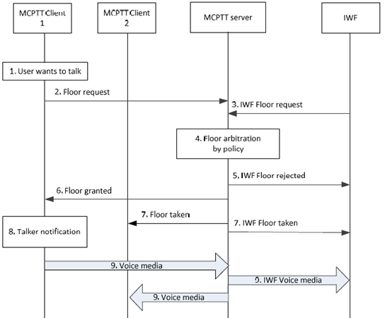
Figure 10.5.6-1 shows the procedure for floor control on an interworking group homed in the MCPTT system, and the LMR system is configured for local floor control request filtering. Simultaneous floor requests are included to show various aspects of interworking floor control.
Pre-conditions:
- The interworking group is homed in the MCPTT system.
- The interworking group is previously defined on the group management server.
- MCPTT client 1, MCPTT client 2, and LMR users (represented by the IWF) are affiliated to that group.
- An interworking group call is ongoing involving MCPTT users and LMR users (represented by the IWF). The floor is currently idle.
Step 1.
The user of MCPTT Client 1 wants to send voice media over the session. At the same time a user in the LMR system (represented by the IWF) wants to also send voice media over the session.
Step 2.
MCPTT Client 1 sends a floor request message to the MCPTT floor control server.
Step 3.
The IWF sends a floor request message to the MCPTT floor control server.
Step 4.
Since the group is homed in the MCPTT system the MCPTT floor control server performs final floor control determination. In this case the MCPTT floor control server determines to accept the floor request from MCPTT Client 1 based on local policy and arbitration results (e.g., according to time of arrival of the request versus the competing request from the IWF).
Step 5.
The IWF is notified that its floor request was rejected.
Step 6.
The MCPTT floor control server sends a floor granted message to MCPTT client 1.
Step 7.
The MCPTT floor control server sends a floor taken message to both MCPTT client 2 and the IWF to inform them of who is granted the floor.
Step 8.
MCPTT Client 1 notifies the user that he/she has been granted the floor and may begin speaking.
Step 9.
MCPTT Client 1 begins sending voice media over the established session. The media is distributed to affiliated group members including the IWF.
10.5.7 Floor control without local filtering on an interworking group defined in the LMR system p. 112
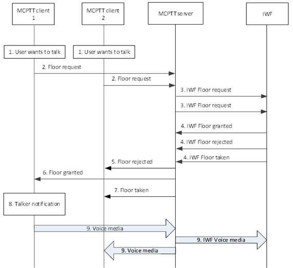
Figure 10.5.7-1 shows the procedure for floor control on an interworking group defined in the LMR system where local filtering is not performed by the MCPTT server. Simultaneous floor requests are included to show various aspects of interworking floor control.
Pre-conditions:
- The interworking group is defined in the LMR system.
- The MCPTT system is configured to send competing floor control requests to the LMR system (represented by the IWF) for floor control arbitration.
- MCPTT client 1, MCPTT client 2, and LMR users are affiliated to that group.
- An interworking group call is ongoing involving MCPTT users and LMR users. The floor is currently idle.
Step 1.
The users of MCPTT client 1 and MCPTT client 2 both want to send voice media over the session.
Step 2.
MCPTT clients 1 and 2 send floor request messages to the MCPTT floor control server.
Step 3.
Since the group is defined in the LMR system the MCPTT floor control server forwards these floor requests to the IWF for final floor control determination. The IWF performs floor arbitration in conjunction with the LMR system (not shown). The IWF determines that the floor can be granted to MCPTT client 1.
Step 4.
The IWF sends an IWF floor granted message for MCPTT client 1, an IWF floor rejected message for MCPTT client 2, and an IWF floor taken message for MCPTT client 2 to the MCPTT floor control server.
Step 5.
The MCPTT floor control server sends a Floor rejected message to MCPTT client 2 to notify the user that his/her floor request was rejected.
Step 6.
The MCPTT floor control server sends a Floor granted message to MCPTT client 1.
Step 7.
The MCPTT floor control server sends a Floor taken message to MCPTT client 2 to notify the user of who is granted the floor.
Step 8.
MCPTT client 1 notifies the user that he/she has been granted the floor and may begin speaking.
Step 9.
MCPTT client 1 begins sending voice media over the established session. The media is distributed to affiliated group members including the IWF.
10.5.8 Floor control without local filtering on an interworking group defined in the MCPTT system p. 114
Figure 10.5.8-1 shows the procedure for floor control on an interworking group defined in the MCPTT system where local filtering is not performed by the LMR system. Simultaneous floor requests are included to show various aspects of interworking floor control.
Pre-conditions:
- The interworking group is defined in the MCPTT system.
- MCPTT client 1, MCPTT client 2, and LMR users are affiliated to that group.
- The LMR system (represented by the IWF) is configured to send all competing floor control requests to the MCPTT system for floor control arbitration.
- The IWF is not affiliating on behalf of LMR users. All LMR group affiliations are passed through the IWF to the MCPTT server.
- An interworking group call is ongoing involving MCPTT users and LMR users. The floor is currently idle.
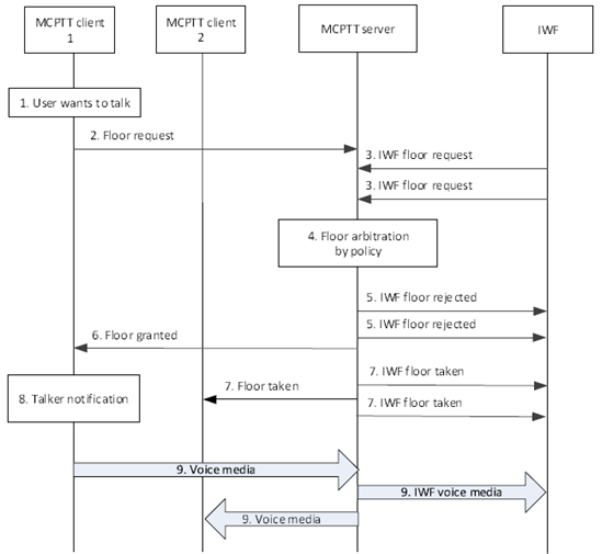
Step 1.
The user of MCPTT client 1 wants to send voice media over the session. At the same time multiple users in the LMR system (represented by the IWF) want to also send voice media over the session.
Step 2.
MCPTT client 1 sends a floor request message to the MCPTT floor control server.
Step 3.
The IWF sends floor request messages to the MCPTT floor control server for each LMR user requesting the floor. In this case two LMR users are requesting the floor. These floor requests contain the MCPTT ID of the LMR user (converted by the IWF).
Step 4.
Since the group is defined in the MCPTT system the MCPTT floor control server performs final floor control determination. In this case the MCPTT floor control server determines to accept the floor request from MCPTT client 1 based on local policy and arbitration results (e.g., according to priority of the request versus the competing requests from the IWF).
Step 5.
The IWF is notified that its floor requests were rejected. The MCPTT floor control server sends an IWF floor rejected message to the IWF for each floor request.
Step 6.
The MCPTT floor control server sends a floor granted message to MCPTT client 1.
Step 7.
The MCPTT floor control server sends floor taken messages to MCPTT client 2 and the IWF to inform them of who is granted the floor. In this case a floor taken message is sent to the IWF corresponding to each affiliated LMR user.
Step 8.
MCPTT client 1 notifies the user that he/she has been granted the floor and may begin speaking.
Step 9.
MCPTT client 1 begins sending voice media over the established session. The media is distributed to affiliated group members including the LMR users.
10.5.9 Floor control in private call controlled by the LMR system |R16| p. 115
Figure 10.5.9-1 shows a procedure for a private call with floor control where the LMR system controls the floor. A request for transmission by the MCPTT user while the LMR user has the floor is rejected by the IWF, to show various aspects of interworking floor control.
Pre-conditions:
- A private call has been set up between an LMR user and MCPTT client 1.
- The LMR system is controlling the floor, via the IWF.
- MCPTT client 1 has the floor.
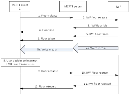
Step 1.
The user of MCPTT Client 1 finishes transmission and MCPTT client 1 releases the floor.
Step 2.
The MCPTT server informs the IWF of the floor release.
Step 3.
The IWF indicates that the floor is now idle.
Step 4.
MCPTT client 1 is informed that the floor is idle.
Step 5.
The IWF indicates that the floor has been taken by the LMR user.
Step 6.
The MCPTT server informs MCPTT client 1 that the floor has been taken by the LMR user.
Step 7.
Media flows from the LMR user to the IWF (7a) and on to MCPTT client 1 (7b).
Step 8.
The user of MCPTT client 1 decides to interrupt the transmission from the LMR user.
Step 9.
MCPTT Client 1 sends a floor request with an appropriate priority to request interruption of the transmission from the LMR user.
Step 10.
The MCPTT server forwards the floor request to the IWF.
Step 11.
The LMR system rejects the request, and the IWF informs the MCPTT server of the rejection.
Step 12.
The MCPTT server informs MCPTT client 1 that the request for interruption has been rejected.
10.5.10 Floor control in private call controlled by the MCPTT system |R16| p. 116
Figure 10.5.10-1 shows a procedure for a private call with floor control where the MCPTT system controls the floor. A request for transmission by the LMR user while the MCPTT user has the floor is accepted by the MCPTT server, to show various aspects of interworking floor control.
Pre-conditions:
- A private call has been set up between the LMR user and MCPTT client 1.
- The MCPTT server is controlling the floor.
- The floor is idle.
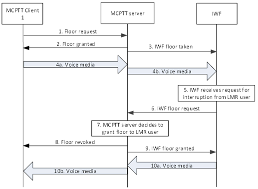
Step 1.
MCPTT Client 1 requests the floor.
Step 2.
The MCPTT server grants the floor to MCPTT Client 1.
Step 3.
The MCPTT server informs the IWF that the floor has been granted to MCPTT client 1.
Step 4.
MCPTT client 1 sends voice media to the MCPTT server (4a) which forwards the voice media to the IWF (4b).
Step 5.
The LMR user decides to interrupt the transmission from MCPTT client 1, and the IWF is informed.
Step 6.
The IWF sends a floor request to the MCPTT server with sufficient priority to interrupt MCPTT client 1.
Step 7.
The MCPTT server decides to allow the interruption from the LMR user, based on the priority of the request and on configuration.
Step 8.
The MCPTT server informs MCPTT Client 1 that the transmission permission has been revoked.
Step 9.
The floor is granted to the LMR user via the IWF.
Step 10.
Voice media is sent from the LMR user via the IWF to the MCPTT server (10a) and on to MCPTT client 1 (10b).