Content for TS 23.271 Word version: 18.0.0
1…
5…
6…
6.2…
7…
8…
9…
9.1.1A…
9.1.2…
9.1.5…
9.1.6…
9.1.8…
9.1.9…
9.1.12…
9.1.13…
9.1.15…
9.1.19…
9.2…
9.2.2…
9.2.3…
9.3…
9.4…
9.5…
9.6…
10…
11…
A…
B…
E
F…
9.3 LCS signalling procedures specified in UTRAN and GERAN Stage 2
9.3a LCS signalling procedures applicable to E-UTRAN
9.3a.1 UE Assisted and UE Based Positioning and Assistance Delivery
9.3a.2 Network Assisted and Network Based Positioning Procedure
9.3a.3 Obtaining Non-UE Associated Network Assistance Data
9.3a.4 Broadcasting Network Assistance Data
9.3a.5 Delivery of Ciphering Keys to UEs for Broadcast Assistance Data
...
...
9.3 LCS signalling procedures specified in UTRAN and GERAN Stage 2 p. 134
9.3a LCS signalling procedures applicable to E-UTRAN |R9| p. 134
9.3a.1 UE Assisted and UE Based Positioning and Assistance Delivery p. 134
The following procedure depicts a positioning service transaction that is used by the E-SMLC to support UE based positioning, UE assisted positioning and delivery of assistance data. A single location request from the MME may invoke one or more transactions, in which each transaction may perform a single positioning service (e.g. UE assisted positioning, UE capability retrieval). RAN positioning procedures related to E-SMLC and UE communication are specified in TS 36.355.
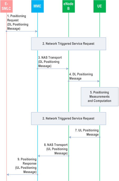
Precondition:
A Correlation identifier allocated by MME had been passed to the E SMLC when the location session (i.e. EPC MT LR, EPC MO LR, or ECP NI LR) was initiated. The Correlation identifier must be assigned such that it can be used to identify the E SMLC serving the location session.
Step 1.
The E-SMLC sends a Location Information message to the MME carrying a Downlink Positioning Information and the Correlation identifier which may request location information from the UE, provide assistance data to the UE or query for the UE capabilities.
Step 2.
If the UE is not using Control Plane CIoT EPS Optimisation and if the UE is in ECM-IDLE state (e.g. if the S1 connection was previously released due to data and signalling inactivity), the MME performs a network triggered service request as defined in TS 23.401 in order to establish a signalling connection with the UE.
If the UE is using Control Plane CIoT EPS Optimisation, procedures for Mobile Terminated Data Transport in Control Plane CIoT EPS optimisation as defined in TS 23.401 are performed by the MME to establish a signalling connection with the UE.
Step 3.
The MME forwards the Downlink Positioning Information to the serving eNodeB in a NAS Transport message conveyed by the S1-AP Transport Message. The MME includes a Routing identifier, in the NAS transport message, representing the Correlation identifier associated with the location session between the MME and E-SMLC.
Step 4.
The eNodeB forwards the Downlink Positioning Information and Routing identifier to the UE by NAS Transport Message.
Step 5.
The UE stores any assistance data provided in the Downlink Positioning Information and performs any positioning measurements and location computation requested by the Downlink Positioning Information.
NB-IoT UEs may perform measurements for some positioning methods only when in ECM-IDLE state. In this case, the UE delays performing positioning measurements in step 5 until after the UE enters ECM-IDLE state.
Step 6.
If the UE is not using Control Plane CIoT EPS Optimisation and if the UE is in ECM-IDLE state, the UE instigates a UE triggered service request or, when User Plane CIoT EPS optimization applies, the Connection Resume procedure as defined in TS 23.401 in order to establish a signalling connection with the MME.
If the UE is using Control Plane CIoT EPS Optimisation, procedures for Mobile Originated Data Transport in Control Plane CIoT EPS optimisation as defined in TS 23.401 are performed by the UE to establish a signalling connection with the MME.
Step 7.
The UE returns any location information obtained in step 5 or returns any capabilities requested in step 4 to the eNodeB in an Uplink Positioning Information included in the NAS Transport message. The Uplink Positioning Information may alternatively carry a request for further assistance data. The UE shall also include the Routing identifier in the NAS Transport Message received in step 4.
Step 8.
The eNodeB forwards the Uplink Positioning Information and Routing identifier to the MME in a NAS Transport message.
Step 9.
The MME forwards the Uplink Positioning Information and the Correlation identifier to the E-SMLC, based on the received Routing identifier, in a Positioning Response. Steps 6 to 9 may be repeated if the UE needs to send multiple messages to respond to the request received in Step 4. Steps 1 to 9 may be repeated to send new assistance data, and to request further location information and further UE capabilities.
9.3a.2 Network Assisted and Network Based Positioning Procedure p. 135
The following procedure is used by the E-SMLC to support network assisted and network based positioning. RAN positioning procedures related to E-SMLC and eNodeB communication are specified in TS 36.455.
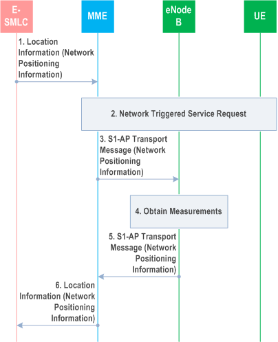
Precondition:
A Correlation identifier allocated by the MME had been passed to the E SMLC when the location session (i.e. EPC MT LR, EPC MO LR, or EPC NI LR) was initiated.
Step 1.
The E-SMLC sends a Location Information message to the MME carrying Network Positioning Information and Correlation identifier which may request location information for the UE from the E-UTRAN.
Step 2.
If the UE is not using Control Plane CIoT EPS Optimisation Data Transport in Control Plane CIoT EPS Optimisation and if the UE is in ECM-IDLE state (e.g. if the S1 connection was previously released due to data and signalling inactivity), the MME performs a network triggered service request as defined in TS 23.401 in order to establish a signalling connection with the UE.
If the UE is using Control Plane CIoT EPS Optimisation, procedures for Mobile Terminated Data Transport in Control Plane CIoT EPS optimisation as defined in TS 23.401 are performed by the MME to establish a signalling connection with the UE.
Step 3.
The MME sends a Network Positioning Information message conveyed in a S1-AP Transport Message to the serving eNodeB for the UE. The MME includes a Routing identifier in the S1-AP Transport Message, representing the E-SMLC associated with the location session.
Step 4.
The eNodeB obtains any location information for the UE requested in step 3.
Step 5.
The eNodeB returns a Network Positioning Information message to the MME, conveyed in a S1-AP Transport Message, containing the location information obtained in step 4. The eNodeB shall also include the Routing identifier in the S1-AP Transport Message received in step 3.
Step 6.
The MME returns the Network Positioning Information received in step 5 to the E-SMLC based on the received Routing identifier. Steps 1 to 6 may be repeated to request further location information and further E-UTRAN capabilities.
9.3a.3 Obtaining Non-UE Associated Network Assistance Data p. 137
The following procedure is used by the E-SMLC to support network assisted and network based positioning. This procedure is not associated with a UE location session. It is used in a MME LCS stateless manner to obtain network assistance data from an eNodeB. RAN positioning procedures related to E-SMLC and eNodeB communication are specified in TS 36.455.
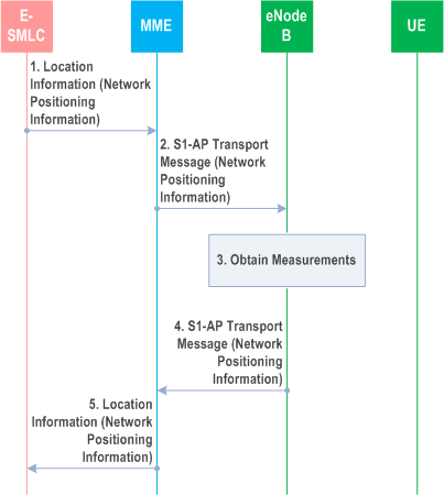
Step 1.
The E-SMLC sends a Location Information message to the MME carrying a Network Positioning Information which may request eNodeB position related information from the E-UTRAN. The target eNodeB identity and E-SMLC identity are included for MME routing purposes.
Step 2.
The MME sends a Network Positioning Information message to the eNodeB, conveyed in a S1-AP Transport Message. The MME includes a Routing identifier that represents the E-SMLC identity in a S1-AP Transport Message. This Routing identifier is not dynamically retained at the MME (i.e., the MME remains LCS stateless).
Step 3.
The eNodeB obtains position information related to the eNodeB.
Step 4.
The eNodeB returns a Network Positioning Information message to the MME, conveyed in a S1-AP Transport Message containing the location information obtained in step 3. The eNodeB also includes the Routing identifier in a S1-AP Transport Message received in step 2.
Step 5.
The MME returns the Network Positioning Information received in step 4 to the E-SMLC. The MME determines the E SMLC from the Routing identifier received in step 4. Steps 4 and 5 may be repeated, using the same Routing identifier if the eNB has multiple messages to respond to the request in Step 2. Steps 1 to 5 may be repeated to request further location information and further E-UTRAN capabilities.
9.3a.4 Broadcasting Network Assistance Data |R15| p. 137
The following procedure is used by the E-SMLC to support broadcasting of network assistance data to target UEs. This procedure is not associated with a UE location session. It is used in a MME LCS stateless manner to send network assistance data to an eNodeB for broadcasting by the eNodeB to target UEs. RAN positioning procedures related to E-SMLC and eNodeB communication are specified in TS 36.455.
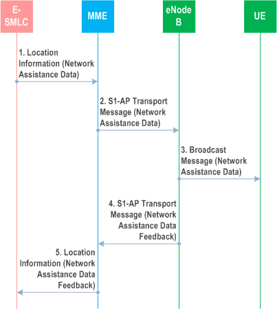
Step 1.
The E-SMLC sends a Location Information message to the MME carrying a Network Assistance Data message. The Network Assistance Data message includes assistance data which may be optionally ciphered. The target eNodeB identity and E-SMLC identity are included for MME routing purposes.
Step 2.
The MME sends the Network Assistance Data message to the eNodeB, conveyed in a S1-AP Transport Message. The MME includes a Routing identifier that represents the E-SMLC identity in a S1-AP Transport Message. This Routing identifier is not dynamically retained at the MME (i.e., the MME remains LCS stateless).
Step 3.
The eNodeB broadcasts the assistance data contained in the Network Assistance Data message.
Step 4.
The eNodeB may return a Network Assistance Data Feedback message to the MME, conveyed in a S1-AP Transport Message. The eNodeB also includes the Routing identifier in a S1-AP Transport Message received in step 2.
Step 5.
The MME returns the Network Assistance Data Feedback message received in step 4 to the E-SMLC. The MME determines the E SMLC from the Routing identifier received in step 4.
9.3a.5 Delivery of Ciphering Keys to UEs for Broadcast Assistance Data |R15| p. 138
The following procedure depicts a procedure that is used by the E-SMLC and the MME to distribute ciphering keys to UEs to enable UEs to decipher broadcast assistance data that was ciphered by the E-SMLC. This procedure is not associated with a UE location session. The procedure makes use of the Attach and Tracking Area Update (TAU) procedures defined in TS 23.401.
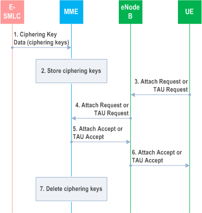
Step 1.
The E-SMLC sends a Ciphering Key Data message to the MME carrying one or more ciphering keys used to cipher network assistance data that is broadcast to UEs according to the procedure in clause 9.3a.4. For each ciphering key, the E-SMLC includes a ciphering key value, a ciphering key identifier, a validity period, a set of applicable tracking areas and a set of applicable types of broadcast assistance data.
Step 2.
The MME stores the ciphering keys including the validity periods, applicable tracking areas and the types of applicable broadcast assistance data.
Step 3.
A UE sends an Attach Request or a TAU Request to the eNodeB. The Attach Request or TAU Request may be sent as part of normal mobility management, A TAU request may also be sent specifically to request and obtain ciphering keys. The UE includes in the Attach Request or TAU Request an indication that ciphering keys are requested. Other details of the Attach Request and TAU Request are as defined in TS 23.401.
Step 4.
The eNodeB forwards the Attach Request or TAU Request to the serving MME.
Step 5.
The serving MME returns an Attach Accept or TAU Accept to the eNodeB as defined in TS 23.401. The MME includes in the Attach Accept or TAU Accept one or more ciphering keys applicable to the current tracking area for the UE. The MME also includes for each ciphering key the ciphering key value, the ciphering key identifier, the validity period, the set of applicable tracking areas and the set of applicable types of broadcast assistance data.
Step 6.
The eNodeB forwards the Attach Accept or TAU Accept to the UE. The UE may start to use each ciphering key to decipher network assistance data that is broadcast according to the procedure in clause 9.3a.4 once the validity period for the ciphering key has started and if the UE is currently in an applicable tracking area. The UE shall cease using a ciphering key when entering a tracking area not applicable to the ciphering key. The UE shall cease using and shall delete a ciphering key when the validity period for the ciphering key has expired.
Step 7.
The MME deletes all information for a ciphering key when the validity period has expired.