Content for TS 23.271 Word version: 18.0.0
1…
5…
6…
6.2…
7…
8…
9…
9.1.1A…
9.1.2…
9.1.5…
9.1.6…
9.1.8…
9.1.9…
9.1.12…
9.1.13…
9.1.15…
9.1.19…
9.2…
9.2.2…
9.2.3…
9.3…
9.4…
9.5…
9.6…
10…
11…
A…
B…
E
F…
6 LCS Architecture p. 34
6.0 Introduction |R13| p. 34
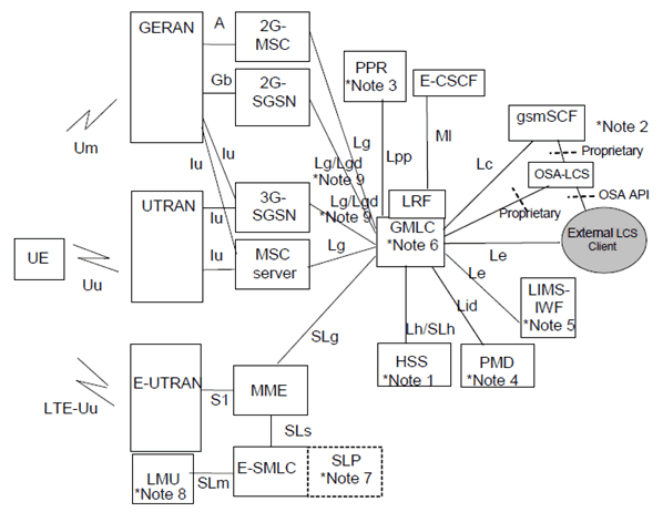
Figure 6.1-1 shows the general arrangement of the Location Service feature in GSM, UMTS and EPS. This illustrates, generally, the relation of LCS Clients and servers in the core network with the GERAN, UTRAN and E-UTRAN Access Networks. The LCS entities within the Access Network communicate with the Core Network (CN) across the A, Gb, Iu and S1 interfaces. Communication among the Access Network LCS entities makes use of the messaging and signalling capabilities of the Access Network.
As part of their service or operation, the LCS Clients may request the location information of UE. There may be more than one LCS client. These may be associated with the GSM/UMTS/EPS networks or the Access Networks operated as part of a UE application or accessed by the UE through its access to an application (e.g. through the Internet).
The clients make their requests to a LCS Server. There may be more than one LCS Server. The client must be authenticated and the resources of the network must be co-ordinated including the UE and the calculation functions, to estimate the location and optionally, velocity of the UE and result returned to the client. As part of this process, information from other systems (other Access Networks) can be used. As part of the location information returned to the client, an estimate of the accuracy of the estimate and the time-of-day the measurement was made may be provided.

![Reproduction of 3GPP TS 23.271, Fig. 6.1-1a: General arrangement of LCS for I-WLAN defined in TS 23.234 [52]](../img/tinv-23-271-6.1-1a.gif)
![Reproduction of 3GPP TS 23.271, Fig. 6.1-2: General arrangement of LCS with inter-GMLC and LIMS-IWF [Lr] interface](../img/tinv-23-271-6.1-2.gif)
6.1 Schematic functional description of LCS operations p. 37
The allocation of LCS functional blocks to the Client, LCS server, Core Network, Access Network and UE is based on the schematic functional description below. The detailed functions and interactions are specified later in the present document and in TS 36.305 for E-UTRAN, TS 25.305 for UTRAN, in TS 43.059 for GERAN and in corresponding Stage 3 specifications.
The operation begins with a LCS Client requesting location information for a UE from the LCS server. The LCS server will pass the request to the LCS functional entities in the core network. The LCS functional entities in the core network shall then:
- verify that the LCS Client is authorized to request the location of the UE or subscriber;
- verify that LCS is supported by the UE;
- establish whether it is allowed to locate the UE or subscriber, for privacy or other reasons;
- establish which network element in the Access Network for GERAN or UTRAN, or EPC for E-UTRAN, should receive the Location request;
- request the Access Network (via the A, Gb or Iu interface) for GERAN or UTRAN, or the E-SMLC (via the SLs interface) for E-UTRAN, to provide location information for an identified UE, with indicated QoS;
- receive information about the location of the UE from the Access Network or E-SMLC and forward it to the Client;
- send appropriate accounting information to an accounting function.