Content for TS 23.259 Word version: 18.0.0
7.3 PN access control procedure in the IM CN subsystem
7.3.1 General
7.3.2 PN access control based on query logic in the IM CN subsystem
7.3.3 PN access control based on access control lists
7.3 PN access control procedure in the IM CN subsystem p. 34
7.3.1 General p. 34
An inherent problem in the Access control list case is the need for the PN-user to configure each originating UE that the PN-user feels appropriate. This may not be a scalable solution where tens of UEs may try to access the controllee UE. In order to solve this problem, the PN-user may configure a controller UE, after processing of this decision normal session initiation procedures may be continued. Once the controller UE has been chosen, to handle all session initiation requests from UEs whose identities are not configured in the access control list, a query can be directed to the particular controller UE.
The controller UE in turn is capable of checking the access control information of this query. Options may be given to the PN-user to either accept the call himself, or answer the query by allowing the call to go through to the intended destination (controllee UE) or deny the call. In addition the user may be given an option of saving this policy for future call requests by the same source. Once the user makes the decision, a response message carrying this information may be sent directing the session back to the original destination.
The PNM AS receives the response message from the S-CSCF. If the decision of the PN-user was to allow the call, it sends the original initial request message. If required to save (based on user response) it saves the settings for the originating UE in the access control list
7.3.2 PN access control based on query logic in the IM CN subsystem p. 34
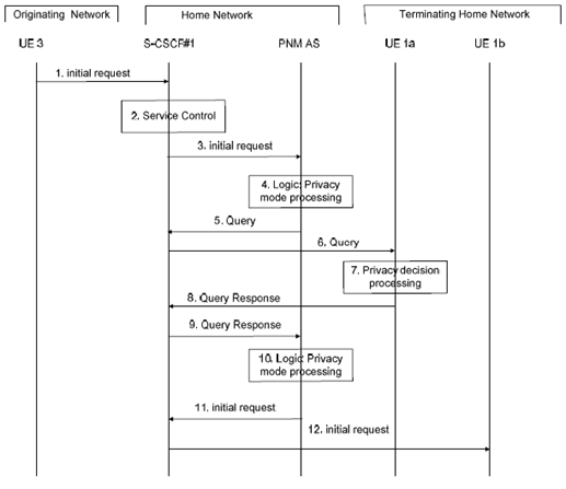
In Figure 7.3.2-1 it is assumed that the originating UE (i.e., UE 3) is not configured in the access control list of the controllee UE (i.e., UE 1b). When the PNM AS receives an Initial Request from S-CSCF# 1, the PNM AS verifies whether UE 3 matches an entry in the access control list of UE 1b. In this case, the PNM AS sends a Query to the controller UE1a to determine the handling.

Step 1.
UE 3 sends an Initial Request towards UE 1b.
Step 2.
S CSCF#1 invokes whatever service logic is appropriate for this session setup attempt.
Step 3.
In this case, the initial filter criterion is triggered and the initial request message is forwarded to the corresponding PNM AS.
Step 4.
The PNM AS receives the initial request and the privacy mode processing is executed.
The PNM AS extracts the source and destination addresses. It confirms that the destination UE is a controllee UE. Using this as a key, it searches its database for the particular PN to find if UE 3 is configured in the access control list as allowed to initiate sessions with UE 1b.
If the originating UE has been configured in the access control list, normal processing is continued. If there is no information regarding the address of the originating UE, the PNM AS may then send a Query to the controller UE, i.e., UE 1a in this example, containing the access request of UE 1b by UE 3. This Query can be processed by UE 1a.
Step 5.
As a result of Step 4, the PNM AS queries the controller UE about the information of how to precede with the Initial Request by sending a Query to S-CSCF#1.
Step 6.
S CSCF#1 validates the service profile, and invokes any termination service logic required for UE 1a and forwards the Query to UE 1a.
Step 7.
In the privacy decision processing, the information contained in the Query is indicated to the PN-user. (Example: UE 3 calling UE 1b, 1: Allow, 2: Deny 3: Allow and save policy 4: Deny and save policy 5: Accept). The PN-user may then allow/disallow and possibly save this option for future calls. This information is sent in the Query Response.
Step 8.
The decision of the user is sent in the Query Response.
Step 9.
The S CSCF#1 forwards the Query Response towards the PNM AS.
Step 10.
In the privacy response processing step, the PNM AS determines the action directed by the user. If the PN-user has allowed the Initial Request to pass to the UE 1b, the Initial Request is sent to UE 1b.
Step 11.
The PNM AS sends the original Initial Request to the S-CSCF#1
Step 12.
The S-CSCF#1 forwards the initial request message to UE 1b.
7.3.3 PN access control based on access control lists p. 35
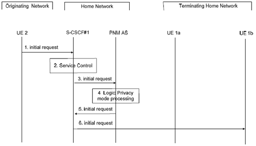
In Figure 7.3.3-1 it is assumed that the originating UE (i.e., UE 2) is configured in the access control list of the controllee UE (i.e., UE 1b). When the PNM AS receives an Initial Request from S-CSCF# 1, the PNM AS verifies whether UE 2 matches an entry in the access control list of UE 1b. In this case, the PNM AS sends the Initial Request message to UE 1b.

Step 1.
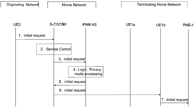
In Figure 7.3.3-2 it is assumed that the originating guest UE (i.e., UE 2) is configured in the access control list of the controllee PNE (i.e., PNE-1). UE1b and PNE-1 form a PAN. When the PNM AS receives an Initial Request from S-CSCF# 1, the PNM AS verifies whether UE 2 matches an entry in the access control list of PNE-1. In this case, the PNM AS sends the Initial Request message to the PNE-1 via UE 1b.
S-CSCF#1 receives an Initial Request from UE 2 to UE 1b.
Step 2.
S-CSCF#1 invokes the termination service control logic required for the UE 1b and evaluates the initial filter criteria.
Step 3.
S-CSCF#1 forwards the Initial Request to the PNM AS as a result of executing the initial filter criteria.
Step 4.
In the privacy mode processing step, the PNM AS extracts the source and destination addresses. It confirms that UE 1b is a controllee UE. Using this as a key, it searches its database for the PN of UE 1b to find if UE 2 is configured in the access control list. In this case, it is assumed that UE 2 is allowed to initiate sessions with UE 1b.
Step 5.
The PNM AS sends the Initial Request message to the S-CSCF#1.
Step 6.
The S-CSCF#1 routes the Initial Request message to the UE 1b.

Step 1.
S-CSCF#1 receives an Initial Request from UE 2 containing the identity of PNE-1.
Step 2.
S-CSCF#1 invokes the termination service control logic required and evaluates the initial filter criteria.
Step 3.
S-CSCF#1 forwards the Initial Request to the PNM AS as a result of executing the initial filter criteria.
Step 4.
In the privacy mode processing step, the PNM AS extracts the source and destination addresses. It confirms that PNE-1 is a controllee PNE. Using this as a key, it searches its database for the PN of PNE to find if UE 2 is configured in the access control list. In this case, it is assumed that UE 2 is allowed to initiate sessions with PNE-1.
Step 5.
The PNM AS sends the Initial Request message to the S-CSCF#1.
Step 6.
PNE-1 accesses the network via UE1b, then the S-CSCF#1 routes the Initial Request message to the UE 1b.
Step 7.
The UE1b sends the Initial Request message to the PNE-1 via the PAN internal interface.