Content for TS 23.246 Word version: 18.0.0
D Shared MBMS Network over E-UTRAN
D.1 General
D.2 Architecture
D.2.1 Architecture for per PLMN MBSFN synchronization area
D.2.2 Reference Points
D.2.3 UE Aspects
D.2.4 TMGI for shared MBMS networks
D (Normative) Shared MBMS Network over E-UTRAN |R18| p. 72
D.1 General p. 72
A Shared MBMS network (SMN) consists of network elements shared by multiple PLMNs to offer MBMS service over E-UTRAN. The shared network elements are at least a shared BM-SC and shared MBMS GW. Shared MBMS Network has MBMS synchronization area (MBSFN area) defined within each PLMN.
The SMN has the following properties:
- The BM-SC and MBMS GW are shared among participating PLMNs.
- The SMN provides the entry point of the data stream.
- The BM-SC can provide full service layer functionality or act only in transparent mode for the case of MBMS as transport only.
- An MBMS service area may span across RAN nodes from different participating PLMNs.
- RAN nodes (eNBs/MCEs) dedicated to MBMS bearer service may be deployed, in which case these nodes are part of the SMN. This deployment requires a shared MME function.
D.2 Architecture p. 72
D.2.1 Architecture for per PLMN MBSFN synchronization area p. 72
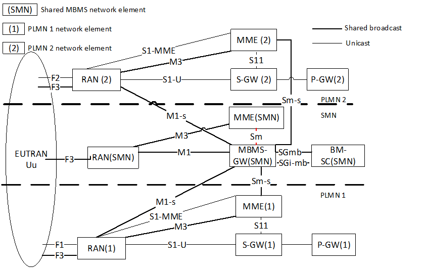
Figure D.2.1-1 shows and example network architecture for Shared MBMS Network with MBMS synchronization area defined within each PLMN. The example shows two PLMNs (PLMN 1 and PLMN2) providing shared MBMS service. In the example, F3 is shared spectrum used by all involved PLMN for MBMS service.

Figure D.2.1-1: Shared MBMS Network architecture with per-PLMN MBMS synchronization area
(⇒ copy of original 3GPP image)
(⇒ copy of original 3GPP image)
The SMN contains the following network elements:
-
Shared BM-SC (denoted BM-SC(SMN) in Figure D.2.1-1):
- Provides all the functionality defined in clause 5.1 for EPC.
-
Shared MBMS-GW (denoted MBMS-GW(SMN) in Figure D.2.1-1)
- Provides all the functionality defined in clause 5.9.1.
-
In addition:
- It connects to MMEs from one or multiple PLMNs via the inter-PLMN Sm-s reference point for control plane signalling.
- It connects to E-UTRAN nodes from one or multiple PLMNs via the inter-PLMN M1-s reference point for IP multicast distribution.
-
Shared E-UTRAN - eNB, MCE (denoted RAN(SMN) in Figure D.2.1-1)
- Provides functionality as defined in clause 5.9.1.
-
Shared MME MBMS function (denoted MME(SMN)):
- The shared MME MBMS control function provides the functionality defined in clause 5.9.2.
D.2.2 Reference Points p. 73
The following reference points are defined for Shared MBMS Network:
- All internal reference points within the SMN leverage existing reference points M1, M2, M3, Sm, SGmb, SGi-mb.
- All internal reference points within each PLMN existing reference points M2, M3
-
M1-s:
- Inter-PLMN reference point between the Shared MBMS GW and the E-UTRAN node from a participating PLMN.
- Provides equivalent functionality to M1.
-
Sm-s:
- Inter-PLMN reference point between the Shared MBMS GW and MME from a participating PLMN.
- Provides equivalent functionality to Sm.
D.2.3 UE Aspects p. 74
Different scenarios can be supported from the perspective of the UE. The following is a non-exhaustive list of possible scenarios:
UE Scenario 1:
The UE receives both unicast and broadcast service from same PLMN. The UE follows the same functionality as defined in clause 5.2.
UE Scenario 2:
The UE receives broadcast MBMS service without PLMN subscription over E-UTRAN without the need to access and register with the PLMN offering the MBMS service. The UE acts in Receive Only mode as defined in Annex E.
UE Scenario 3:
The UE receives unicast service from one serving PLMN's (e.g. the PLMN for which it has unicast subscription), and receive MBMS service through a different PLMN. The UE acts in Receive Only mode with independent unicast as defined in Annex E.
D.2.4 TMGI for shared MBMS networks p. 74
AS described in TS 23.003, the TMGI is composed by an MBMS Service ID and a PLMN ID (MCC/MNC).
There construction of the PLMN ID field in the TMGI is deployment dependent. The following are example deployment options:
-
Example Deployment Option 1: Shared PLMN ID
- A Shared PLMN ID is used for the shared MBMS service. The shared PLMN ID is broadcasted in the cells broadcasting the shared MBMS service content.
-
Example Deployment Option 2: Internal PLMN ID in the Shared MBMS network
- The Shared MBMS network (i.e. BMSC) uses the "Internal" PLMN ID to generate the TMGI. MBMS-GW uses the PLMN ID from the incoming SGmb interface towards the rest of the network entities in the MBMS path. eNB announces a MBMS session TMGI whose PLMN ID is not in the SIB1 PLMN ID list. The "Internal" PLMN ID is not used for any other PLMN services.