Content for TS 23.221 Word version: 18.0.0
8 Support of IM CN Subsystem services
8.1 Context activation and registration
8.2 Location management
8.3 IMS Emergency sessions
9 Efficient use of radio resource
...
...
8 Support of IM CN Subsystem services |R5| p. 41
8.1 Context activation and registration p. 41
The IP address is allocated to UE either by GPRS specific signalling when a PDP context is activated using the PDP Context Activation Procedure, or some other means e.g. by DHCP. The UE shall use IP addresses assigned to it for, but not limited to, the following:
- the exchange of application level signalling (e.g., registration, CC) with the S-CSCF from the access network currently used,
- application level registration to IM CN subsystem as an address used to reach the UE
- an address used to reach the UE for multimedia sessions.

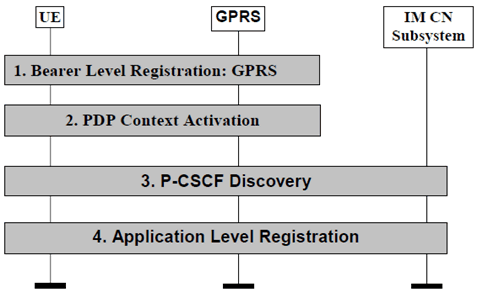
The following steps are performed:
Step 1.
There can be time gaps between these procedures and the following one. For instance, the UE may perform PDP context activation and the P-CSCF discovery, but not the application level registration. The UE may use the activated PDP context for other types of signalling, e.g. for P-CSCF discovery.
the bearer level registration is performed (e.g. when the terminal is switched on or upon explicit indication from the user).
Step 2.
the PDP context activation is done. The UE has two options:
Step 3.
- activate a PDP context using the PDP Context Activation Procedure and obtain a new IP address (e.g. if the UE does not have any existing PDP context active or desires to use a different IP address)
- activate an additional PDP context using the Secondary PDP Context Activation Procedure and re-using the IP address of the linked already active PDP contexts.
UE performs the P-CSCF discovery procedure, where the UE discovers a P-CSCF, TS 23.228.
Step 4.
Whether the procedures are activated individually by the UE or some of them are performed automatically depends on implementation of the terminal and on the UE's configuration. For instance, the multimedia application in the UE could start the application level registration and steps 2-4 would have to be executed in response to support the operation initiated by the application. Interaction with the UE may happen during these steps.
UE performs application level registration by providing the IP address obtained at step 2 to the P-CSCF selected at step 3. The IP address used for signalling purposes is allocated in association with PDP context activation and not on an incoming call basis.
The discovered P-CSCF forwards the registration on to the UE's home network where a S-CSCF, TS 23.228 is assigned and the registration takes place. This registration associates the P-CSCF with the UE.
From the S-CSCF point of view, the P-CSCF is where the UE is reachable for mobile-terminated session control signalling and any other type of mobile terminated IMS signalling.
8.2 Location management p. 43
8.2.1 Registration concepts for a subscriber roaming into CS domain p. 43
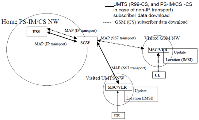
Figure 8.2 shows the registration concept for a subscriber, who access IM services in the home network, roaming into a CS domain.

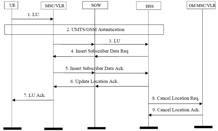
The detailed message sequence chart for a subscriber roaming into a CS domain and accessing an IM application is shown in Figure 8.3.

Step 1.
The UE initiates the Location Update procedure with the MSC/VLR of the visited network. The LU message contains the IMSI of the subscriber.
Step 2.
The authentication is performed as per the existing 3GPP specifications for the CS domain.
Step 3.
The MSC/VLR initiates the MAP Location Update procedure towards the HSS of the user via SGW. The HSS stores the VLR address etc. The message contains IMSI and other parameters as defined in the 3GPP specifications for the CS domain. The SGW performs SS7 transport to/from IP conversion.
Step 4.
The HSS provides the subscriber data for the roaming user to VLR by sending MAP Insert Subscriber Data message via SGW. The message contains IMSI and other necessary parameters as defined in the 3GPP specification for both Iu and A/Gb mode. The message is passed through the SGW transparently while the SS7 to/from IP conversion is performed in SGW.
Step 5.
The serving VLR then acknowledges the receipt of the subscriber data to the HSS via SGW.
Step 6.
The HSS acknowledges the completion of location updating procedure to the MSC/VLR via SGW.
Step 7.
The MSC/VLR acknowledges the completion of location updating procedure to the UE.
Step 8.
The HSS sends the MAP Cancel Location message to the old MSC/VLR (optional procedure).
Step 9.
Location cancellation is acknowledged to the HSS by the old MSC/VLR.
8.3 IMS Emergency sessions |R7| p. 45
8.3.1 GPRS/EPS considerations for UE recognized IMS Emergency Sessions p. 45
Requirements for GPRS and EPS functions for support of IMS emergency services are defined in TS 23.060, TS 23.401 and in TS 23.167.
8.3.2 Emergency Calls in absence of UICC for GPRS/EPS Access p. 45
9 Efficient use of radio resource |R5| p. 45
This clause captures the technical requirements to ensure efficient use of the radio resource in the UMTS access network. The radio resource is considered to be a scarce resource and therefore every opportunity shall be taken to optimize its use.
For UTRAN it shall be possible to re-apply PS domain pre-release 5 mechanisms for efficient use of radio resource.
Additional requirements for efficient use of the radio spectrum for release 5 SIP signalling include the following:
- UMTS shall support mechanisms to optimize transport of SIP signalling packets over the radio interface, typically by compressing the SIP signalling messages and by compressing the IP and transport layer protocol headers that carry these SIP messages.
- The chosen solution(s) shall be extensible to facilitate the incorporation of new and improved compression algorithms in a backward compatible way as they become available.
- The chosen solution(s) should work in roaming scenarios.
- Application specific compression shall minimize impacts on existing UMTS release e.g. it could be defined between the UE and associated application server, e.g. at the SIP Client and at the first SIP Proxy.