Content for TS 23.009 Word version: 18.0.0
1…
4…
4.3…
6…
6.2…
6.2.3
6.3…
7…
7.2…
8…
8.1.3…
8.2…
8.2.2…
8.2.4
8.3…
8.3.2…
9…
10…
11…
12…
12.8…
12.8.2
12.8.3
13…
14…
15…
8.2.4 Procedure for subsequent GSM to UMTS handover not requiring a circuit connection p. 69
As for the subsequent GSM to UMTS handover with a circuit connection, the same two cases of subsequent handover apply:
- the UE/MS moves back to the area of 3G_MSC-A;
- the UE/MS moves into the area of a third 3G_MSC (3G_MSC-B').
8.2.4.1 Description of subsequent GSM to UMTS handover procedure without circuit connection i): MSC-B to 3G_MSC-A p. 70
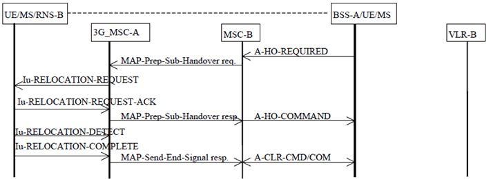
The procedure for successful GSM to UMTS handover from MSC-B back to 3G_MSC-A without circuit connection is shown in Figure 28. The only difference with the Figure 26, is that no circuit release is needed between 3G_MSC-A and MSC-B.

Figure 28: Subsequent GSM to UMTS handover procedure i): Successful handover from MSC-B to 3G_MSC-A not requiring a circuit connection
(⇒ copy of original 3GPP image)
(⇒ copy of original 3GPP image)
8.2.4.2 Description of subsequent GSM to UMTS handover procedure without circuit connection ii): MSC-B to 3G_MSC-B' p. 70
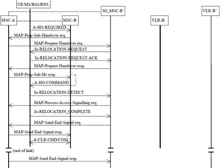
The procedure for successful GSM to UMTS handover from MSC-B to 3G_MSC-B' is shown in Figure 29.
The procedure consists of two parts:
- a subsequent handover from MSC-B back to MSC-A as described in subclause 7.4.1 (the same procedures apply if MSC-A is replaced by 3G_MSC-A); and
- a basic GSM to UMTS handover from MSC-A to 3G_MSC-B' as described in subclause 8.2.2.

Figure 29: Subsequent GSM to UMTS handover procedure ii): Successful handover from MSC-B to 3G_MSC-B' without circuit connection
(⇒ copy of original 3GPP image)
(⇒ copy of original 3GPP image)