Content for TR 22.837 Word version: 19.4.0
0…
4
5…
5.2…
5.3…
5.4…
5.5…
5.6…
5.7…
5.8…
5.9…
5.10…
5.11…
5.12…
5.13…
5.14…
5.15…
5.16…
5.17…
5.18…
5.19…
5.20…
5.21…
5.22…
5.23…
5.24…
5.25…
5.26…
5.27…
5.28…
5.29…
5.30…
5.31…
5.32…
6…
7…
5.28 Use case on Vehicles Sensing for ADAS
5.28.1 Description
5.28.2 Pre-conditions
5.28.3 Service Flows
5.28.4 Post-conditions
5.28.5 Existing features partly or fully covering the use case functionality
5.28.6 Potential New Requirements needed to support the use case
...
...
5.28 Use case on Vehicles Sensing for ADAS p. 76
5.28.1 Description p. 76
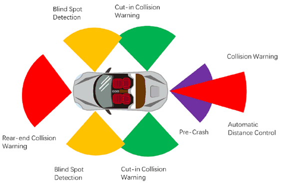
Advanced Driving Assistance System(ADAS) uses various sensors (Wireless Sensing millimeter wave radar, lidar, monocular / binocular camera and satellite navigation) installed on the vehicle to sense the surrounding environment at any time during the driving process, collect data, identify, detect and track static and dynamic objects, and carry out systematic calculation and analysis in combination with navigation map data, so as to make the driver aware of the possible dangers in advance, and effectively increase the comfort and safety of driving.

There is an opportunity for 3GPP New Radio (NR) based sensing technologies to be added into ADAS. 5G based wireless sensing service could improve the ADAS reliability and quality.
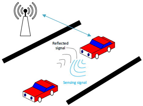
The ADAS has the map information, the real time location/ trajectory of the car and can assist the car driving, e.g. stop the car for avoiding collision. The car (as 3GPP UE) is equipped with 3GPP NR based sensing technology. When the UE initially accesses the 5G network, the UE is authorized by the 5G network to participate in sensing under the operator's control. The 3GPP sensing data is from the NR based sensor, and the sensing result is sent to the ADAS system of the car. Collaborating with other non-3GPP sensing devices/technologies, NR based sensing result as input to ADAS could improve the comfort and safety of driving.
The vehicle as a 3GPP UE based sensing sensor is important for automotive use cases, it can operate under network control & complements network-based sensing. Network based sensing alone cannot fully address the automotive use case needs, e.g.:
- There may be a blockage from the network (base station) to the sensed target.
- ADAS concerns more on relative positioning other than absolute position. Network based sensing introduces additional errors (due to compounding errors of two separate positions).
- Automobiles applications may determine sensing priority/performance requirements locally (not visible to gNB).
| Parameter | Typical Automotive Radar KPIs | |
|---|---|---|
| Long Range Radar
[10] [12] [20] [50] [51] [52] |
Short Range Radar
[10] [12] [20] [52] [53] [54] |
|
| Maximum range | 250-300m (for RCS of 10dBsm with >90%detection probability) | 30-100m |
| Range resolution | 10-75cm | 5-20cm |
| Range accuracy | ±10 to ±40cm | ±2 to 10cm |
| FOV azimuth | ±9-15deg | ±60-85deg |
| Azimuth resolution | 1-3deg | 3-9deg |
| Azimuth accuracy | ±0.1-0.3deg | ±0.3-5deg |
| Update rate | 5 to 20 fps | 20 to 50 fps |
| Max one-way velocity | ±50m/s to ±70m/s | ±30m/s |
| Velocity resolution | 0.1 -0.6 m/s | 0.1 - 0.6 m/s |
| Velocity accuracy | ±0.03m/s to ±0.12 m/s | ±0.03m/s to ±0.12 m/s |
Although all vehicles on the road are expected to be equipped with NR radio, but not necessarily utilizing them for 100 percent of time. Enabling NR radio based sensing for ADAS can be a better utilization of the capability and radio resources.
5.28.2 Pre-conditions p. 77
The 3GPP UE in the car has 3GPP subscription and is authorized by the operator to perform sensing.
5.28.3 Service Flows p. 78

- Tom buys a new car with the latest ADAS equipped.
- Tom wants to drive the car from home to the company in the morning of a working day. Tom drives from home to the road. The 3GPP NR based sensor in Tom's car transmits the 3GPP NR signal to the other car(s) in the same road, and receives the reflected signal to detect the distance and speed of the other car(s) to feed to the ADAS in Tom's car.
- While the car is driving on the highway, suddenly a car is stopped before the Tom's car due to an accident, fortunately it is timely detected by the NR based sensor.
- The NR based sensors send the collision warning to the ADAS, the ADAS stops the car immediately.
- Finally, Tom's car avoids a collision accident and leaves the highway safely.
5.28.4 Post-conditions p. 78
With the safely driving experience provided by ADAS, Tom arrives in the company safely and easily. Tom starts the daily work in the office.
5.28.5 Existing features partly or fully covering the use case functionality p. 78
There are features of Sidelink positioning for the car moving along the LOS road (e.g., using Sidelink positioning for car ranging on the same road), which requires the participant cars are 3GPP UEs.
5.28.6 Potential New Requirements needed to support the use case p. 78
[PR 5.28.6-1]
The 5G system shall be able to configure and authorize UEs supporting V2X applications to perform sensing.
[PR 5.28.6-2]
The 5G system shall be able to collect charging information for UEs supporting V2X applications when performing sensing.
[PR 5.28.6-3]
The 5G system shall be able to support the following KPIs:
| Scenario | Sensing service area | Confidence level [%] | Accuracy of positioning estimate by sensing (for a target confidence level) | Accuracy of velocity estimate by sensing (for a target confidence level) | Sensing resolution | Max sensing service latency[ms] | Refreshing rate [s] | Missed detection [%] | False alarm [%] | |||
|---|---|---|---|---|---|---|---|---|---|---|---|---|
| Horizontal
[m] |
Vertical [m] | Horizontal [m/s] | Vertical [m/s] | Range resolution [m] | Velocity resolution (horizontal/ vertical) [m/s x m/s] | |||||||
| ADAS [long range Radar] | Outdoor | [95] | [≤1.3]
NOTE 2 | ≤0.5 | [≤ 0.12]
NOTE 4 | N/A | [0.4]
NOTE 5 | [≤ 0.6]
NOTE 4 | [50] | [≤ 0.2] | [≤ 10] | [<1] |
| ADAS [Short range Radar] | Indoor (parking space)/Outdoor | [95] | [≤2.6]
NOTE 3 | ≤0.5 | [≤ 0.12]
NOTE 4 | N/A | [0.4]
NOTE 5 | [≤ 0.6]
NOTE 4 | [20] | [≤ 0.05] | [≤ 10] | [<1] |
|
NOTE 1:
The terms in Table 5.28.6-1 are found in clause 3.1.
NOTE 2:
Assuming typical max range of 250m, range accuracy of 10cm, azimuth accuracy of ±0.3deg. Positioning accuracy as (Min-Max) within field of view.
NOTE 3:
Assuming typical max range of 30m, range accuracy of 2cm, azimuth accuracy of ±5deg.Positioning accuracy as (Min-Max) within field of view.
NOTE 4:
Velocity accuracy and resolution is typically reported for the radial velocity (not absolute H/V velocity).
NOTE 5:
Range resolution typically reported as 3D ranging distance accuracy.
|
||||||||||||