Content for TS 23.433 Word version: 19.0.0
0…
4…
7…
8…
9.2…
9.2.2.3…
9.2.3…
9.2.4…
9.3…
9.3.2.2…
9.3.3…
9.3.4…
9.4…
9.5…
9.5.3…
9.5.4…
9.6…
9.7…
9.7.3…
9.7.4…
9.8…
9.9…
9.10…
A…
C…
9.6 SEALDD server relocation
9.6.1 General
9.6.2 Procedures
9.6.2.1 SEALDD context transfer
9.6.2.2 SEALDD relocation in EDN
9.6.3 Information flows
9.6.3.1 SEALDD context push request
9.6.3.2 SEALDD context push response
9.6.3.3 SEALDD context pull request
9.6.3.4 SEALDD context pull response
9.6.4 APIs
9.6.4.1 General
9.6.4.2 Sdd_DDContext_Push Request operation
9.6.4.3 Sdd_DDContext_Pull Request operation
...
...
9.6 SEALDD server relocation p. 58
9.6.1 General p. 58
The SEALDD server may be relocated due to UE mobility or load re-balance.
If SEALDD server is adapted to EDGEAPP as an EAS, the EAS relocation procedure can be used to support SEALDD server relocation for both UE mobility and SEALDD server load re-balance. If SEALDD is not adapted to EDGEAPP, for UE mobility, the SEALDD client can discover (e.g. using DNS) a new SEALDD server in the target area and establish a new SEALDD communication channel including the old SEALDD communication channel information. For load re-balance, the SEALDD server can discover (e.g. using DNS) an equivalent SEALDD server and communicate with the new SEALDD server.
Based on existing service continuity mechanism supported by 3GPP core network (e.g. BP/ULCL), during SEALDD server relocation with UPF change, the new UPF takes care of the existing unfinished application traffic flow towards the old VAL server and inter-UPF tunnel is used to forward the traffic. For new application traffic flow which may have UE's new IP address as source IP address, the new SEALDD server sends it directly to the new VAL server.
For SEALDD server relocation, the inter-SEALDD server communication via SEALDD-E reference point is needed, which transfers the SEALDD context from the old SEALDD server to the new SEALDD server.
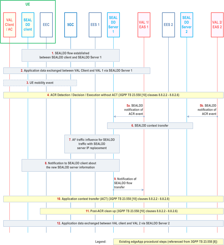
The following procedures detail the EDGEAPP ACT part between old SEALDD server (i.e. S-EAS) and new SEALDD server (i.e. T-EAS) as described in clause 8.8.2.2 to clause 8.8.2.6 of TS 23.558. Also, a high-level flow is provided to show the scenario used in EDN.
9.6.2 Procedures p. 59
9.6.2.1 SEALDD context transfer p. 59
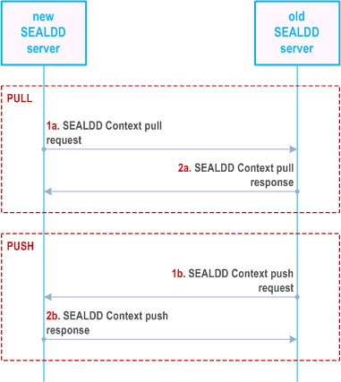
Figure 9.6.2.1-1 describes SEALDD context transfer procedure in pull (step 1a and 2a) or push (step 1b and 2b) operation.
Pre-conditions:
- For pull operation, the old SEALDD server endpoint is available in the new SEALDD server
- For push operation, the new SEALDD server endpoint is available in the old SEALDD server.

The transferred SEALDD context includes the service subscription information created upon VAL server's interaction for requesting SEALDD transmission service (e.g. step 1 and 2 in Figure 9.2.2.1-1), and also the SEALDD client and SEALDD server communication tunnel management information (e.g. UE IP address) which is created upon SEALDD client's interaction for requesting data transmission (e.g. step 5 and 6 in Figure 9.2.2.1-1). If new SEALDD server supports transportation layer service continuity, additional transport layer context (e.g. TCP/TLS/QUIC) is transferred from old SEALDD server to new SEALDD server. If the new SEALDD Server is not provisioned with the VAL server configured SEALDD policy, then it can pull from the Old SEALDD server via the pull operation. The push operation does not support the transfer of the VAL server configured SEALDD policy between Old and New SEALDD server.
The new SEALDD server, after receiving the SEALDD context from the old SEALDD server, allocates IP address and port for SEALDD-Uu user plane communication. The new SEALDD server also sends back to the old SEALDD server with the allocated endpoint information If operation is push. Then the old SEALDD server can request 5GC to perform IP replacement procedure, as defined in clause 6.3.3 of TS 23.548. The request includes the traffic descriptor of old SEALDD server (i.e., SEALDD-UU address/port), the traffic descriptor of new SEALDD server (i.e., SEALDD-UU address/port) and/or the target DNAI.
Optionally, after receiving the SEALDD context with the SEALDD-UU endpoint from the old SEALDD server, the new SEALDD server can request 5GC to perform IP replacement procedure.
9.6.2.2 SEALDD relocation in EDN p. 60
Pre-conditions:
- VAL Server 1 and 2 are adapted to the EDGEAPP as EAS.
- VAL Server 1 and 2 register its associated SEALDD server in EES as described in clause 9.4.3.2.

Step 1.
An application client on a UE, acting as a VAL client, establishes a SEALDD flow over SEALDD-UU to send application data to VAL Server 1. SEALDD client and SEALD server 1 maintain SEALDD flow information (e.g., SEALDD flow ID, VAL IDs/addresses, VAL requirements).
Step 2.
Application data is sent via the SEALDD flow between the VAL Client and VAL Server 1.
Step 3.
The UE moves and generates a mobility event in the 5GC.
Step 4.
The UE's mobility event triggers the execution of an Application Context Relocation (ACR) procedure as described in TS 23.558; or VAL server 1 triggers ACR due to load re-balancing reason. Any of the ACR scenarios detailed in clauses 8.8.2.2 - 8.8.2.6 of TS 23.558 may occur. In this step, the first three phases of the ACR procedure are performed, up to ACT. In this step VAL Server 1 acts as EAS 1 and VAL Server 2 as EAS 2, therefore participating in corresponding signalling. VAL server 2 has been selected as SEALDD-enabled server meeting the ACR criteria to be the target EAS. The associated SEALDD server 2 has also been selected and may support transportation layer (e.g. UDP/TCP/QUIC) service continuity.
Step 5a.
Before triggering ACT, VAL Server 1 sends a SEALDD notification of ACR event to SEALDD Server 1.
Step 5b.
Before triggering ACT, VAL Server 2 sends a SEALDD notification of ACR event to SEALDD Server 2.
Step 6a.
SEALDD server 1 transfers the SEALDD context to the SEALDD server 2 which serves VAL Server 2 as described in clause 9.6.2.1, with push operation. The SEALDD server 1 can obtain the SEALDD server 2 endpoint for SEALDD-Uu user plane to the SEALDD client, as specified in clause 9.6.2.1.
Step 6b.
SEALDD server 2 can obtain the SEALDD context from the SEALDD server 1 by using the pull operation, as described in clause 9.6.2.1.
Step 7.
SEALDD server 1 applies the functionality specified in clause 5.2.6.7 of TS 23.502 for AF traffic influence, providing the N6 routing information for the SEALDD client and SEALDD server 2. The SEALDD server 1 may:
Step 8.
- If the SEALDD server 2 supports transportation layer service continuity, additionally includes SEALDD IP replacement information (i.e. SEALDD server 1 endpoint and SEALDD server 2 endpoint for SEALDD-Uu user plane) in the AF traffic influence. Since the UE is not aware of SEALDD server change, the new SEALDD traffic (due to new VAL traffic sent by VAL client) is sent by UPF towards the new SEALDD server, this handling in UPF is agnostic to the SEALDD server 2. Or,
- send AF traffic influence with target DNAI of SEALDD server 2, and simultaneous connectivity indicator, to request 5GC to maintain the simultaneous connectivity over source PSA and target PSA with source SEALDD server and target SEALDD server, as described in clause 6.3.4 of TS 23.548.
If the SEALDD server 2 has no transportation layer service continuity support, a SEALDD Connection info update notification is sent to SEALDD client, e.g. to update the allocated IP address and port for SEALDD-Uu user plane communication. Then the SEALDD client acknowledges the received SEALDD Connection info update notification. After SEALDD client is aware of the new SEALDD-Uu IP address and port, it starts to send new SEALDD traffic (received from the VAL client) over the new connection. The new SEALDD server maps the received SEALDD traffic to the application traffic according to the SEALDD traffic descriptor and VAL service ID. The new SEALDD server sends the recovered application traffic to new VAL server. The downlink application traffic sent from the new VAL server to VAL client is processed similarly.
Step 9.
SEALDD Server 1 notifies VAL Server 1 of the completion of the SEALDD flow transfer.
Step 10.
VAL Server 1 (acting as EAS1) and VAL Server 2 (acting as EAS 2) execute the Application Context Transfer (ACT) procedure step corresponding to the pending ACR scenario (clauses 8.8.2.2 - 8.8.2.6 of TS 23.558), which is out the 3GPP scope.
Step 11.
The post-ACR clean-up phase is executed, as described in the corresponding ACR scenario (clauses 8.8.2.2 - 8.8.2.6 of TS 23.558).
Step 12.
The application data from the VAL Client is sent via the SEALDD flow (with SEALDD server 2) to VAL Server 2.
9.6.3 Information flows p. 62
9.6.3.1 SEALDD context push request p. 62
Table 9.6.3.1-1 describes the information flow from the old SEALDD server to the new SEALDD server to push the SEALDD context.
| Information element | Status | Description |
|---|---|---|
| Requestor ID | M | Identifies the requestor (i.e. old SEALDD server). |
| SEALDD-Uu Context | M | Identifies the context related to SEALDD-Uu connection, which is created upon SEALDD connection establishment. |
| SEALDD-S Context | M | Identifies the context related to SEALDD-S subscription. |
| Transport layer context | O | Identifies the context related to Transport layer (e.g. TCP/TLS/QUIC) for SEALDD-Uu user plane communication. |
9.6.3.2 SEALDD context push response p. 62
Table 9.6.3.2-1 describes the information flow from the new SEALDD server to the old SEALDD server for responding to the SEALDD context push request.
| Information element | Status | Description |
|---|---|---|
| Result | M
(NOTE) | Success or failure. |
| New SEALDD server endpoint | O | The endpoint (IP address and port) on the new SEALDD for SEALDD-Uu user plane communication. |
|
NOTE:
The result is failed if the new SEALDD server rejects the relocation for SEALDD client.
|
||
9.6.3.3 SEALDD context pull request p. 63
Table 9.6.3.3-1 describes the information flow from the new SEALDD server to the old SEALDD server to pull the SEALDD context.
| Information element | Status | Description |
|---|---|---|
| Requestor ID | M | Identifies the requestor (i.e. new SEALDD server). |
| SEALDD policy indication | O | Indicates the need to transfer the VAL server configured SEALDD policy. |
9.6.3.4 SEALDD context pull response p. 63
Table 9.6.3.4-1 describes the information flow from the old SEALDD server to the new SEALDD server for responding to the SEALDD context pull request.
| Information element | Status | Description |
|---|---|---|
| Result | M | Success or failure. |
| SEALDD-Uu Context | M | Identifies the context related to SEALDD-Uu connection, which is created upon SEALDD connection establishment. |
| SEALDD-S Context | M | Identifies the context related to SEALDD-S subscription. |
| Transport layer context | O | Identifies the context related to Transport layer (e.g. TCP/TLS/QUIC) for SEALDD-Uu user plane communication. |
| SEALDD policy | O | Indicates the VAL server configured SEALDD policy. |
9.6.4 APIs p. 63
9.6.4.1 General p. 63
Table 9.6.4.1-1 illustrates the APIs exposed by SEALDD server for UE's service continuity.
| API Name | API Operations | Operation Semantics | Consumer(s) |
|---|---|---|---|
| Sdd_ | Push Request | Request/Response | SEALDD server |
| Pull Request | Request/Response | SEALDD server |
9.6.4.2 Sdd_DDContext_Push Request operation p. 63
API operation name:
Sdd_DDContext_Push Request
Description:
The consumer requests to push SEALDD context.
Inputs:
See clause 9.6.3.1.
Outputs:
See clause 9.6.3.2
See clause 9.6.2.1 for details of usage of this operation.
9.6.4.3 Sdd_DDContext_Pull Request operation p. 64
API operation name:
Sdd_DDContext_Pull Request
Description:
The consumer requests to pull SEALDD context.
Inputs:
See clause 9.6.3.3.
Outputs:
See clause 9.6.3.4
See clause 9.6.2.1 for details of usage of this operation.