Content for TS 23.433 Word version: 19.0.0
0…
4…
7…
8…
9.2…
9.2.2.3…
9.2.3…
9.2.4…
9.3…
9.3.2.2…
9.3.3…
9.3.4…
9.4…
9.5…
9.5.3…
9.5.4…
9.6…
9.7…
9.7.3…
9.7.4…
9.8…
9.9…
9.10…
A…
C…
9.3 SEALDD enabled E2E redundant transmission
9.3.1 General
9.3.2 Procedure
9.3.2.1 E2E redundant transmission path establishment procedure
...
...
9.3 SEALDD enabled E2E redundant transmission p. 36
9.3.1 General p. 36
The following clauses specify procedures, information flow and APIs for SEALDD enabled E2E redundant transmission.
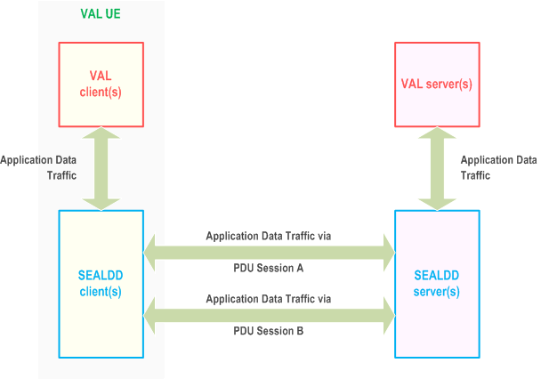
SEALDD client and SEALDD server transfer SEALDD traffic via two redundant PDU sessions as specified in clause 5.33.2.1 of TS 23.501.
Figure 9.3.1-1 shows the data traffic flow of E2E redundant transmission. For uplink data delivery, VAL client sends application traffic to SEALDD client, the SEALDD client duplicates the application packets and maps them into two SEALDD traffic. Then the two SEALDD traffic are transferred to SEALDD server via the two redundant PDU sessions shown in Figure 9.3.1-1. The SEALDD server eliminates the redundant packets and recovers the application traffic. The recovered application traffic is transferred to VAL server by the SEALDD server. For downlink data delivery, VAL server sends application traffic to SEALDD server, the SEALDD server duplicates the application packets and maps them into two SEALDD traffic. The two SEALDD traffic are transferred to UE via the two redundant PDU sessions. The SEALDD client eliminates the redundant SEALDD packets and recovers the application traffic, then sends the application traffic to the VAL client.

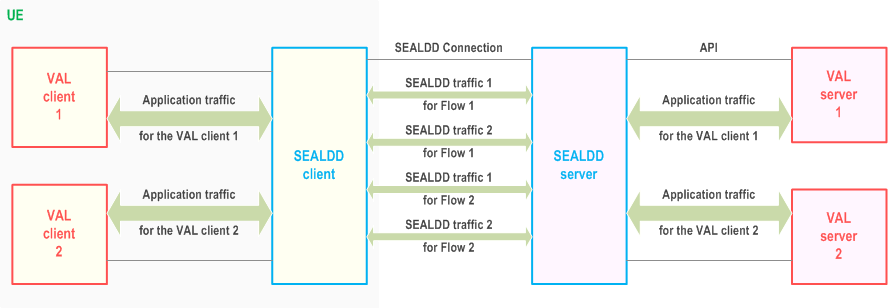
Figure 9.3.1-2 shows the data traffic flow of E2E redundant transmission for multiple VAL servers. In this scenario, SEALDD server and SEALDD client use different SEALDD flow IDs and SEALDD traffic descriptors to identify SEALDD traffic for different VAL servers.

For outbound data delivery, VAL application traffic is sent to SEALDD enabler layer, the SEALDD enabler duplicates the application packets and maps them into two SEALDD traffic (with the same Flow ID). Then according to the SEALDD traffic descriptors of the SEALDD flow, the SEALDD traffic is sent out with different destination addresses or ports and different source addresses or ports. For inbound data delivery, two SEALDD traffic (with different source addresses or ports and different destination addresses or ports) are received. According to the SEALDD traffic descriptors, SEALDD enabler decides they belong to the same Flow. Then after packet elimination and reordering, the two SEALDD traffic is aggregated to one VAL application traffic.
9.3.2 Procedure p. 37
9.3.2.1 E2E redundant transmission path establishment procedure p. 37
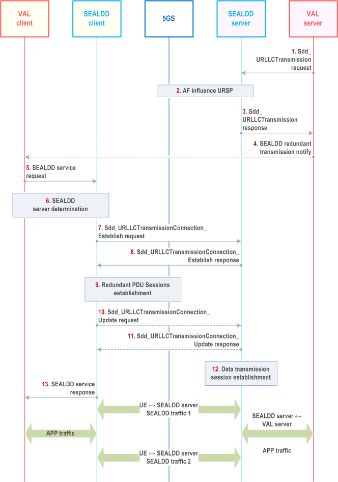
Figure 9.3.2.1-1 illustrates the procedure for redundant transmission establishment. This procedure can be triggered by a VAL server for data transfer per application layer transaction.
Pre-conditions:
- The VAL server has discovered and selected the SEALDD server by CAPIF functions as specified in clause 9.4.2.
- The VAL server has established application connection with the VAL client and can get the VAL client's UE ID or UE address via the application connection.

Step 1.
After the negotiation and establishment of the connections, the SEALDD client gets the mapping information between the application traffic and SEALDD flow ID. The SEALDD server gets the mapping information between the SEALDD flow ID and the SEALDD-S connection. Upon receiving application traffic from VAL client, the SEALDD client duplicates the application packets and maps them into two SEALDD traffic flows with SEALDD traffic descriptors as negotiated with SEALDD server in step 8 and step 10. The two SEALDD traffic is sent through two redundant PDU sessions to the SEALDD server. The SEALDD server maps the two SEALDD traffic to the same application traffic according to the stored SEALDD traffic descriptors, SEALDD client ID and SEALDD flow ID. After packet elimination and reordering the SEALDD server sends the aggregated application traffic to VAL server via the connection established in step 3 according to the mapping information. The downlink application traffic sent from VAL server to VAL client is processed similarly.
The VAL server decides to use SEALDD service to help ensuring data transmission quality for application traffic transfer and send a Sdd_URLLCTransmission request to the SEALDD server discovered by CAPIF. The request includes UE ID/address, VAL server ID, VAL service ID, SEALDD-S Data transmission connection information of the VAL server side, and optionally, the QoS information for the application traffic, e.g. QoS requirements. The VAL server ID and VAL service ID can be used to identify the VAL application traffic.
Step 2.
Upon receiving the request, the SEALDD server decides to establish redundant transmission path. The SEALDD server allocates two different addresses or ports for the two redundant transmission paths and sends an AF request to 5GS to create or update URSP rules as described in clause 4.15.6.10 of TS 23.502 for the UE(s) going to use the redundant transmission service. The AF request includes Identifiers of the UE(s) and application traffic descriptor containing the addresses or ports allocated by SEALDD server. The SEALDD server may send the AF request to provide the required QoS information to 5GC via N33/N5, as defined in clause 5.2.6.9 and in clause 5.2.5.3 of TS 23.502.
Step 3.
If the processing of the request was successful, SEALDD server allocates address/port of the SEALDD server to receive the packets from the VAL server for application data transfer as SEALDD-S data transmission connection information of the SEALDD server side. The SEALDD server responds with a SEALDD service response (including SEALDD-S data transmission connection information of the SEALDD server side) and indicates to the VAL server that redundant transmission service should be activated. The VAL server and SEALDD server can use SEALDD-S data transmission connection information to establish the data transmission connection between VAL server and SEALDD server for application data transfer.
Step 4.
If the redundant transmission requirement is not preconfigured or notified to the VAL client, the VAL server may notify the VAL client(s) which is going to use the redundant transmission service through application layer message.
Step 5.
The VAL client sends a SEALDD service request to use E2E redundant transmission for the application traffic.
Step 6.
The SEALDD client discovers and selects the proper SEALDD server for the VAL application as specified in clause 9.4.3. After this step, the SEALDD client can get the SEALDD server's address.
Step 7.
The SEALDD client allocates a SEALDD flow ID mapping to the application traffic. The SEALDD client sends Sdd_URLLCTransmissionConnection_Establish request to SEALDD server. The request includes the SEALDD client ID, SEALDD flow ID, VAL server ID, VAL service ID for SEALDD server to identify the specific application traffic.
Step 8.
Upon receiving the request, the SEALDD server sends SEALDD traffic descriptor for redundant transmission of the SEALDD server side (i.e. the addresses or ports for the redundant transmission paths allocated in step 2 and the transport protocol used for the SEALDD traffic) to SEALDD client.
Step 9.
The UE uses the SEALDD traffic descriptor of the SEALDD server and the created or updated URSP rules to trigger two redundant PDU Sessions establishment procedure via 5GS as specified in clause 5.33.2.1 of TS 23.501.
Step 10.
[Optional] The SEALDD client sends Sdd_URLLCTransmissionConnection_Update request to SEALDD server. The request includes the SEALDD client ID, the SEALDD flow ID, the SEALDD traffic descriptors for redundant transmission of the SEALDD client side (i.e. UE addresses and ports of the two redundant PDU Sessions). The two redundant SEALDD traffic use the same SEALDD flow ID for identification.
Step 11.
[Optional] The SEALDD server sends a response to SEALDD client. After this step, the SEALDD client and SEALDD server both get the whole SEALDD traffic descriptors (including the UE's addresses/ports and SEALDD server's addresses/ports for the SEALDD traffic transmission). The SEALDD client and SEALDD server store the mapping between the application traffic and SEALDD traffic.
Step 12.
[Optional] If the connection between VAL server and SEALDD server is not established in step 3, the SEALDD server establishes connection with VAL server for the VAL client to transmit application traffic mapping to the redundant SEALDD traffic according to the SEALDD-S information negotiated in step 1-3
Step 13.
The SEALDD client responds with a SEALDD service response.