TS 44.001
MS-BSS interface –
General Aspects and Principles
V18.0.0 (PDF)
2024/03 13 p.
V17.0.0
2022/03 13 p.
V16.0.0
2020/06 13 p.
V15.0.0
2018/06 13 p.
V14.0.0
2017/03 13 p.
V13.0.0
2015/12 13 p.
V12.0.0
2014/09 13 p.
V11.0.0
2012/09 13 p.
V10.0.0
2011/03 13 p.
V9.0.0
2009/12 13 p.
V8.0.0
2008/12 13 p.
V7.0.0
2007/06 13 p.
V6.0.0
2005/01 13 p.
V5.0.0
2002/06 13 p.
V4.1.0
2002/06 13 p.
GSM Rel-99 v8.0.0
2000/02 12 p.
GSM Rel-98 v7.0.0
1999/06 12 p.
GSM Rel-97 v6.0.0
1998/10 12 p.
GSM Rel-96 v5.0.0
1996/10 13 p.
GSM Phase-2 v4.0.4
1996/01 14 p.
GSM Phase-1 v3.0.1
1992/02 11 p.
- Rapporteur:
- Ing. Johansson, Kaj
Ericsson LM
Content for TS 44.001 Word version: 18.0.0
0a Scope
0b References
0c Definitons and abbreviations
1 General
2 Interface applications
3 Interface technical specification objectives
4 Interface characteristics
5 Interface capabilities
6 Technical Specifications on GSM MS-BSS interfaces
7 Protocol modelling principles
$ Change History
0a Scope p. 5
The present document describes the general aspects and principles relating to the Technical Specifications for the GSM MS-BSS interface.
0b References p. 5
The following documents contain provisions which, through reference in this text, constitute provisions of the present document.
- References are either specific (identified by date of publication, edition number, version number, etc.) or non-specific.
- For a specific reference, subsequent revisions do not apply.
- For a non-specific reference, the latest version applies. In the case of a reference to a 3GPP document (including a GSM document), a non-specific reference implicitly refers to the latest version of that document in the same Release as the present document.
[1] Void.
[1a]
TR 21.905: "Vocabulary for 3GPP Specifications".
[2]
TS 22.030: "Man-Machine Interface (MMI) of the User Equipment (UE)".
[3]
TS 24.002: "GSM - UMTS Public Land Mobile Network (PLMN) access reference configuration".
[4]
TS 44.003: "Mobile Station - Base Station System (MS - BSS) interface; Channel structures and access capabilities".
[5]
TS 44.004: "Layer 1; General requirements".
[6]
TS 44.005: "Data Link (DL) layer; General aspects".
[7]
TS 44.006: "Mobile Station - Base Station System (MS - BSS) interface; Data Link (DL) layer specification".
[8]
TS 24.007: "Mobile radio interface signalling layer 3; General aspects".
[9]
TS 24.008: "Mobile radio interface; Layer 3 specification; Core network protocols; Stage 3".
[10]
TS 24.010: "Mobile radio interface layer 3; Supplementary services specification; General aspects".
[11]
TS 24.011: "Point-to-Point (PP) Short Message Service (SMS) support on mobile radio interface".
[12]
TS 44.012: "Short Message Service Cell Broadcast (SMSCB) support on the mobile radio interface".
[13]
ITU-T Recommendation X.200: "Information technology - Open Systems Interconnection - Basic Reference Model: The basic model".
[14]
ITU-T Recommendation X.210: "Information technology - Open systems interconnection - Basic Reference Model: Conventions for the definition of OSI services".
0c Definitons and abbreviations p. 6
Abbreviations used in the present document are listed in TR 21.905.
1 General p. 6
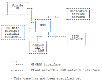
A GSM PLMN supports a wide range of services which a user accesses by a standard set of interfaces at a mobile station (MS). The mobile station is connected to the PLMN fixed infrastructure via a radio path to a base station, as shown in Figure 1.
The MS-BSS interface on this radio path is specified in the 24- and 44-series of Technical Specifications in such a way as to permit user and network technologies and configurations to evolve separately.

The principles and procedures for the man-machine interface (MMI) to the MS are described in Technical Specification TS 22.030. The user may also use standard terminal interfaces within the MS. The reference configuration for the access is described in Technical Specification TS 24.002.
2 Interface applications p. 6
Figure 2 shows some examples of the application of GSM MS-BSS interfaces. The following cases are shown:
- access of simple handportable or vehicle mounted MSs;
- access of an MS with multiple terminal equipment installation;
- access of a mobile PBX or LAN;
- land-line ISDN networks;
- dedicated service networks.

3 Interface technical specification objectives p. 7
MS-BSS interface Technical Specifications should allow:
- different types of mobile stations and terminal equipment to use the same standard interface;
- portability of MSs within the system area of the GSM system;
- separate evolution of both mobile stations and network equipment technologies and configurations;
- calls to a terminal using the same code (call number) no matter in what country it is actually located;
- connections of an MS to the ISDN network so that only the radio channel capacity and the ISDN protocol are limiting factors.
4 Interface characteristics p. 7
The MS-BSS interface is specified by a comprehensive set of characteristics, including:
- channel structures and access capabilities;
- user-network (MS-BSS) protocols;
- maintenance and operation characteristics;
- performance characteristics;
- service characteristics.
5 Interface capabilities p. 8
In addition to the multiservice capability, the GSM MS-BSS interface may allow for capabilities such as the following:
- multidrop and other multiple terminal arrangements;
- choice of informaion bit rate, circuit or packet switching mode, layer 2 coding method, etc., on a call-by-call or other basis (e.g. semipermanent, or subscription time option), over the same interface according to the user's need;
- capability for compatibility checking in order to check whether calling and called terminals can communicate with each other.
6 Technical Specifications on GSM MS-BSS interfaces p. 8
The reference configurations for the GSM MS-BSS interface define the terminology for various reference points. Technical Specification TS 24.002 contains the GSM PLMN access reference configuration.
Technical Specification TS 44.003 defines the channel structures and access capabilities for the MS-BSS interface. A distinction is necessary between the logical channel structure supported by the interface and the access capability supported by the radio path of the system.
The MS-BSS interface as defined in Technical Specifications TS 44.004, TS 44.005, TS 44.006, TS 24.007, TS 24.008, TS 24.010, TS 24.011 and TS 44.012 is applicable to a wide range of situations.
7 Protocol modelling principles p. 8
The signalling protocols on the MS-BSS Interface are specified using the concepts of the reference model of Open System Interconection (OSI) given in ITU-T Recommendations X.200 and X.210.
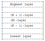
The basic structuring technique in the OSI reference model is layering. According to this technique, communication among application processes is viewed as being logically partitioned into an ordered set of layers represented in a vertical sequence as shown in Figure 3.

Entities exist in each layer. Entities in the same layer, but in different systems which must exchange information to achieve a common objective are called "peer entities". Entities in adjacent layers interact through their common boundary. The services provided by the (N + 1)-layer are the combination of the services and functions provided by the (N)-layer and all layers below the (N)-layer.
Management functions may also be required. They may include functions which are common for several layers and are not supported by the services provided by a specific layer. Examples of such functions are error reporting, status reporting and management of the operation of certain layers. Such management functions do not require that peer-to-peer messages are sent across the MS-BSS interface.
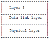
For signalling on the MS-BSS interface three layers are required as shown in Figure 4.

The layers are:
- PHYSICAL LAYER which corresponds to the lowest layer. The functions and protocols of the physical layer are defined in Technical Specification TS 44.004.
- DATA LINK LAYER. The functions and protocols of the data link layer are defined in Technical Specifications TS 44.005 and TS 44.006.
- LAYER 3. The functions and protocols of layer 3 are defined in Technical Specifications TS 24.007, TS 24.008, TS 24.010, TS 24.011 and TS 44.012.

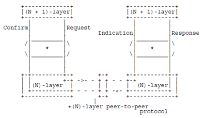
The REQUEST primitive type is used when a higher layer is requesting a service from the next lower layer.
The INDICATION primitive type is used by a layer providing a service to notify the next higher layer of activities related to the primitive type REQUEST.
The RESPONSE primitive type is used by a layer to acknowledge receipt, from a lower layer, of the primitive type INDICATION.
The CONFIRM primitive type is used by the layer providing the requested service to confirm that the activity has been completed.