TS 24.002
GSM-UMTS Public Land Mobile Network (PLMN)
Access Reference Configuration
V18.0.0 (PDF)
2024/03 13 p.
V17.0.0
2020/12 13 p.
V16.0.0
2019/12 13 p.
V15.0.0
2018/06 13 p.
V14.0.0
2017/03 13 p.
V13.0.0
2015/12 13 p.
V12.0.0
2014/09 13 p.
V11.0.0
2012/09 13 p.
V10.0.0
2011/03 13 p.
V9.0.0
2009/12 13 p.
V8.1.0
2009/03 13 p.
V7.0.0
2007/06 13 p.
V6.0.0
2005/01 13 p.
V5.1.1
2003/06 13 p.
V4.1.1
2003/06 13 p.
V3.1.1
2003/06 14 p.
GSM Rel-98 v7.0.0
1999/06 11 p.
GSM Rel-97 v6.0.0
1998/10 10 p.
GSM Rel-96 v5.0.0
1996/04 15 p.
GSM Phase-2 v4.0.4
1996/01 14 p.
GSM Phase-1 v3.0.2
1992/02 10 p.
- Rapporteur:
- Ing. Johansson, Kaj
Ericsson LM
Content for TS 24.002 Word version: 18.0.0
1 Scope p. 5
The present document describes the reference configuration for access to a PLMN.
A user accesses a PLMN via a number of interfaces, including the MS-BS (in A/Gb mode and GERAN Iu mode), UE-UTRAN (in UTRAN Iu mode), UE-E-UTRAN, and UE-5G-AN interface. The purpose of this document is to indicate the possible access arrangements that may be used in conjunction with the MS-BS (in A/Gb mode and GERAN Iu mode), UE-UTRAN (in UTRAN Iu mode), UE-E-UTRAN, and UE-5G-AN interface.
1.1 References p. 5
The following documents contain provisions which, through reference in this text, constitute provisions of the present document.
- References are either specific (identified by date of publication, edition number, version number, etc.) or non specific.
- For a specific reference, subsequent revisions do not apply.
- For a non-specific reference, the latest version applies. In the case of a reference to a 3GPP document (including a GSM document), a non-specific reference implicitly refers to the latest version of that document in the same Release as the present document.
[1] Void.
[2] Void.
[3] Void.
[4] Void.
[5] Void.
[6] Void.
[7] Void.
[8] Void.
[9] Void.
[10] Void.
[11] Void.
[12] Void.
[13] Void.
[14]
TS 44.021: "Rate adaption on the Mobile Station - Base Station System (MS - BSS) interface".
[15] Void.
[16] Void.
[17] Void.
[18] Void.
[19] Void.
[20] Void.
[21] Void.
[22] Void.
[23] Void.
[24] Void.
[25] Void.
[26] Void.
[27] Void.
[28] Void.
[29] Void.
[30] Void.
[31] Void.
[32] Void.
[33]
TS 27.001: "General on Terminal Adaptation Functions (TAF) for Mobile Stations (MS)".
[34]
TS 27.002: "Terminal Adaptation Functions (TAF) for services using asynchronous bearer capabilities".
[35]
TS 27.003: "Terminal Adaptation Functions (TAF) for services using synchronous bearer capabilities".
[36] Void.
[37] Void.
[38] Void.
[39]
TR 21.905: " Vocabulary for 3GPP Specifications ".
[40] Void.
[41]
TS 25.322: "Radio Link Control (RLC) Protocol Specification".
[42]
ITU-T Recommendation V.24 (1996): "List of definitions for interchange circuits between data terminal equipment (DTE) and data circuit terminating equipment (DCE)".
[43]
ITU-T Recommendation V.28 (1993): "Electrical characteristics for unbalanced double current interchange circuits".
[44]
Infrared Data Association IrDA: "IrPHY Physical layer signalling standard".
[45]
Personal Computer Memory Card Association: "PCMCIA 2.1 or PC Card 3.0 electrical specification or later revisions".
[46] Void.
1.2 Abbreviations p. 6
Abbreviations used in the present document are listed in TR 21.905.
2 General definitions p. 6
The following definitions 2.1-2.3 are based on those used for ISDN.
2.1 Reference Configurations p. 7
Reference Configurations are conceptual configurations useful in identifying access arrangements to a network. Two concepts are used in defining reference configurations:
reference points and functional groups.
2.2 Functional Groups p. 7
Functional Groups are sets of functions which may be needed in network access arrangements. In a particular access arrangement, specific functions in a functional group may or may not be present. Specific functions in a functional group may be performed in one or more pieces of equipment.
2.3 Reference Points p. 7
Reference Points are the conceptual points dividing functional groups. In a specific access arrangement, a reference point may correspond to a physical interface between pieces of equipment, or there may not be any physical interface corresponding to the reference point.
2.4 Interface Points p. 7
Interface Points are reference points within a PLMN at which a 3GPP specified interface is always identified.
2.5 Terminal Definitions p. 7
The term 'mobile station' ( MS ) in the present document is synonymous with the term 'user equipment' (UE ) in 3G terminology as defined in TR 21.905.
The term 'TE2' in the present document is synonymous with the term 'TE' in 3G terminology as defined in TR 21.905.
The term 'MT2' in the present document is synonymous with the term 'MT' in 3G terminology as defined in TR 21.905.
3 Reference Configuration p. 8
3.0 General p. 8
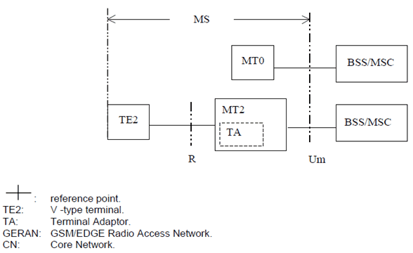
The reference configuration for PLMN (in A/Gb mode and GERAN Iu mode) access interfaces is shown in Figure 1.

Figure 1: PLMN Access Reference Configuration (in A/Gb mode and GERAN Iu mode)
(⇒ copy of original 3GPP image)
(⇒ copy of original 3GPP image)
There are two types of MT:
- MT0 includes functions belonging to the functional group MT, with support of no terminal interfaces.
- MT2 includes functions belonging to the functional group MT, and with an interface that complies with the 3GPP TS 27.00z series Terminal Adaptation Function specifications [33], [34], [35]. Accordingly, the interchange circuit mapping at the MT2 to TE interface shall comply with the ITU-T V.24 [42] recommendation; while the physical implementation shall conform either to the ITU-T V.28 [43], or to the IrDA IrPHY Physical signalling standard specification [44], or to the PCMCIA 2.1 [45], or to the PC-Card 3.0 [45], electrical specification or to later revisions.

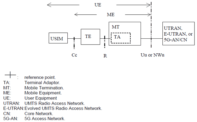
Figure 2: PLMN Access Reference Configuration (UTRAN Iu mode, E-UTRAN, or 5G-AN)
(⇒ copy of original 3GPP image)
(⇒ copy of original 3GPP image)
There is no reference point identified for the TA Function. The TA Function is considered as a part of the Mobile Termination and with an interface that complies with the 3GPP TS 27.00z series Terminal Adaptation Function specifications [33], [34], [35].
3.1 Mobile Termination (MT) p. 9
The MT performs the following functions, which performs the following functions:
- radio transmission termination;
- radio transmission channel management;
- terminal capabilities, including presentation of a man-machine interface to a user;
- speech encoding/decoding;
- error protection for all information sent across the radio path. This includes FEC (forward error correction) and, for signalling and user data (except for transparent data services), ARQ (automatic request for retransmission);
- flow control of signalling and mapping of user signalling to/from PLMN access signalling;
- flow control of user data (except for transparent data services) and mapping of flow control for asynchronous transparent data services;
- rate adaptation of user data (see TS 44.021) and data formatting for the transmission SAP (TS 25.322);
- multiple terminal support;
- mobility management.
3.2 Void
4 Physical Realisation p. 10
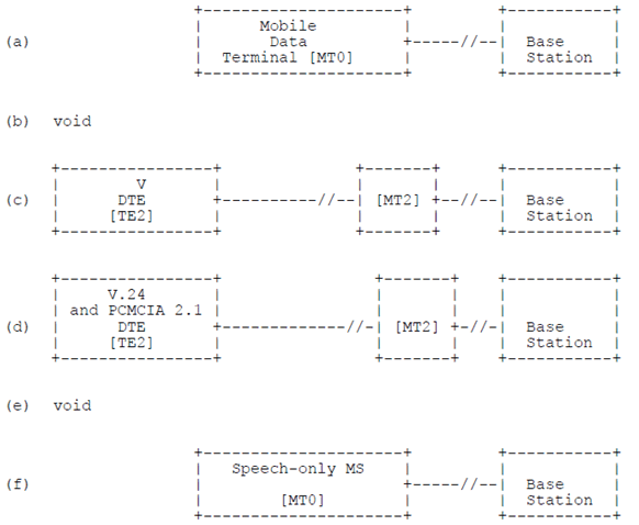
In a PLMN, the reference point Um/Uu is an interface point, i.e. it is always implemented as a physical interface (according to 3GPP Technical Specifications in the 44, 45, 24, 25 and 36 series). The R reference point may be optionally implemented as physical interface. The implementation of interfaces at this reference point is according to TS 27.001, TS 27.002 and TS 27.003.
Figure 3 gives examples of configurations illustrating combinations of physical interfaces at the R reference point. The examples shown are not exhaustive, but only serve to illustrate possible implementations of the respective functional blocks.
Example (a) of Figure 3 illustrates a fully integrated MS including data terminal functions within the mobile station equipment.
Example (c) of Figure 3 illustrates the connection of a TE2 by an ITU-T V series interface according to TS 27.002 and TS 27.003.
Example (d) of Figure 3 illustrates the connection of a MT2 PCMCIA card to a TE2 by a PCMCIA 2.1 interface according to TS 27.002and TS 27.003.
Example (f) of Figure 3 illustrates the connection of a speech only MS.
