Content for TS 38.425 Word version: 18.1.0
5.5 Elements for the NR user plane protocol
5.5.1 General
5.5.2 Frame format for the NR user plane protocol
5.5.3 Coding of information elements in frames
5.5.4 Timers
5.6 Handling of unknown, unforeseen and erroneous protocol data
5.5 Elements for the NR user plane protocol p. 13
5.5.1 General p. 13
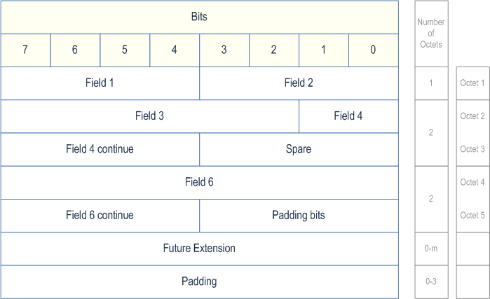
In the present document the structure of frames is specified by using Figures similar to Figure 5.5.1-1.

Unless otherwise indicated, fields which consist of multiple bits within an octet have the most significant bit located at the highest bit position of the field (according to the bit numbers indicated above frame in Figure 5.5.1-1). In addition, if a field spans several octets, most significant bits are located in lower numbered octets (right of frame in Figure 5.5.1-1).
The frame is transmitted starting from the lowest numbered octet. Within each octet, the bits are sent according decreasing bit position (bit position 7 first).
Bits labelled "Spare" should be set to "0" by the sender and should not be checked by the receiver.
The header part of the frame is always an integer number of octets. The payload part is octet aligned (by adding 'Padding Bits' when needed). The total size of the frame shall not exceed 1018 octets (see TS 29.281).
The receiver should be able to remove an additional Future Extension field that may be present.
See description of Future Extension field in clause A.1.
Padding octets may be added at the end of the frame, see Padding in clause 5.5.3.24
5.5.2 Frame format for the NR user plane protocol p. 14
5.5.2.1 DL USER DATA (PDU Type 0) p. 14
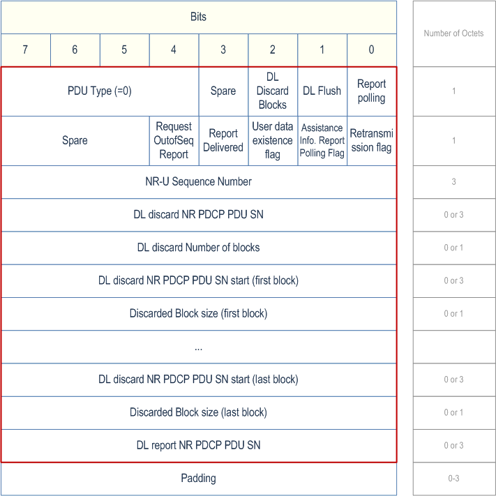
This frame format is defined e.g. to allow the corresponding node to detect lost NR-U packets and may be associated with the transfer of a Downlink PDCP PDU.
The following shows the respective DL USER DATA frame.

5.5.2.2 DL DATA DELIVERY STATUS (PDU Type 1) p. 15
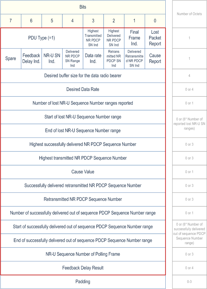
This frame format is defined to transfer feedback to allow the receiving node (i.e. the node that hosts the PDCP entity) to control the downlink user data flow via the sending node (i.e. the corresponding node).
The following shows the respective DL DATA DELIVERY STATUS frame. The Figure shows an example of how a frame is structured when all optional IEs (i.e. those whose presence is indicated by an associated flag) are present.
Absence of such an IE changes the position of all subsequent IEs on octet level.

5.5.2.3 ASSISTANCE INFORMATION DATA (PDU Type 2) p. 17
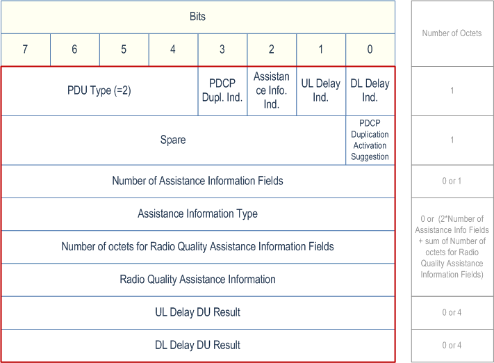
This frame format is defined to allow the node hosting the PDCP entity to receive assistance information.
The following shows the respective ASSISTANCE INFORMATION DATA frame.

5.5.3 Coding of information elements in frames p. 18
5.5.3.1 PDU Type p. 18
Description:
The PDU Type indicates the structure of the NR user plane frame. The field takes the value of the PDU Type it identifies; e.g. "0" for PDU Type 0. The PDU type is in bit 4 to bit 7 in the first octet of the frame.
Value range:
{0=DL USER DATA, 1=DL DATA DELIVERY STATUS, 2= ASSISTANCE INFORMATION DATA, 3-15=reserved for future PDU type extensions}
Field length:
4 bits
5.5.3.2 Spare p. 18
Description:
The spare field is set to "0" by the sender and should not be interpreted by the receiver. This field is reserved for later versions.
Value range:
(0-2n-1).
Field length:
n bits.
5.5.3.3 Report polling p. 18
Description:
This parameter indicates that the node hosting the NR PDCP entity requests providing the downlink delivery status report.
Value range:
{0=Downlink Data Delivery Status report not requested, 1= Downlink Data Delivery Status report requested}.
Field length:
1 bit.
5.5.3.4 NR-U Sequence Number p. 18
Description:
This parameter indicates the NR-U sequence number as assigned by the node hosting the NR PDCP entity.
Value range:
{0..224-1}.
Field length:
3 octets.
5.5.3.5 Desired buffer size for the data radio bearer p. 18
Description:
This parameter indicates the desired buffer size in bytes for the concerned data radio bearer as specified in clause 5.4.2.1.
Value range:
{0..232-1}.
Field length:
4 octets.
5.5.3.6 Desired Data Rate p. 18
Description:
This parameter indicates the amount of data desired to be received in bytes in a specific amount of time (1 s) for a specific data radio bearer established for the UE as specified in clause 5.4.2.1.
Value range:
{0..232-1}.
Field length:
4 octets.
5.5.3.7 DL Flush p. 19
Description:
This parameter indicates the presence of DL discard NR PDCP PDU SN.
Value range:
{0= DL discard NR PDCP PDU SN not present, 1= DL discard NR PDCP PDU SN present}.
Field length:
1 bit.
5.5.3.8 DL discard NR PDCP PDU SN p. 19
Description:
This parameter indicates the downlink NR discard PDCP PDU sequence number up to and including which all the NR PDCP PDUs should be discarded.
Value range:
{0..218-1}.
Field length:
3 octets.
5.5.3.9 DL Discard Blocks p. 19
Description:
This parameter indicates the presence of DL discard Number of blocks, DL discard NR PDCP PDU SN start and Discarded Block size.
Value range:
{0= DL discard Number of blocks, DL discard NR PDCP PDU SN start and Discarded Block size not present, 1= DL discard Number of blocks, DL discard NR PDCP PDU SN start and Discarded Block size present}.
Field length:
1 bit.
5.5.3.10 DL discard NR PDCP PDU SN start p. 19
Description:
This parameter indicates the starting SN of a downlink NR PDCP PDU block to be discarded.
Value range:
{0..218-1}.
Field length:
3 octets.
5.5.3.11 DL discard Number of blocks p. 19
Description:
This parameter indicates the number of NR PDCP PDU blocks to be discarded.
Value range:
{1..244}.
Field length:
1 octet.
5.5.3.12 Discarded Block size p. 19
Description:
This parameter indicates the number of NR PDCP PDUs counted from the starting SN to be discarded.
Value range:
{1..255}.
Field length:
1 octet.
5.5.3.13 Lost Packet Report p. 19
Description:
This parameter indicates the presence of Number of lost NR-U Sequence Number ranges reported, Start of lost NR-U Sequence Number range and End of lost NR-U Sequence Number range.
Value range:
{0= Number of lost NR-U Sequence Number ranges reported, Start of lost NR-U Sequence Number range and End of lost NR-U Sequence Number range not present, 1= Number of lost NR-U Sequence Number ranges reported, Start of lost NR-U Sequence Number range and End of lost NR-U Sequence Number range present}.
Field length:
1 bit.
5.5.3.14 Final Frame Indication p. 20
Description:
This parameter indicates whether the frame is the last DL status report as described in clause 5.4.2.1.
Value range:
{0=Frame is not final, 1= Frame is final}.
Field length:
1 bit.
5.5.3.15 Number of lost NR-U Sequence Number ranges reported p. 20
Description:
This parameter indicates the number of NR-U Sequence Number ranges reported to be lost.
Value range:
{1..161}.
Field length:
1 octet.
5.5.3.16 Start of lost NR-U Sequence Number range p. 20
Description:
This parameter indicates the start of an NR-U sequence number range reported to be lost.
Value range:
{0..224-1}.
Field length:
3 octets.
5.5.3.17 End of lost NR-U Sequence Number range p. 20
Description:
This parameter indicates the end of an NR-U sequence number range reported to be lost.
Value range:
{0..224-1}.
Field length:
3 octets.
5.5.3.18 Highest Delivered NR PDCP SN Ind p. 20
Description:
This parameter indicates the presence of Highest successfully delivered PDCP Sequence Number.
Value range:
{0= Highest successfully delivered PDCP Sequence Number not present, 1= Highest successfully delivered PDCP Sequence Number present}.
Field length:
1 bit.
5.5.3.19 Highest successfully delivered NR PDCP Sequence Number p. 20
Description:
This parameter indicates feedback about the in-sequence delivery status of NR PDCP PDUs at the corresponding node.
Value range:
{0..218-1}.
Field length:
3 octets.
5.5.3.20 Highest Transmitted NR PDCP SN Ind p. 20
Description:
This parameter indicates the presence of the Highest transmitted NR PDCP Sequence Number.
Value range:
{0= Highest transmitted NR PDCP Sequence Number not present, 1= Highest transmitted NR PDCP Sequence Number present}.
Field length:
1 bit.
5.5.3.21 Highest transmitted NR PDCP Sequence Number p. 21
Description:
This parameter indicates the feedback about the transmitted status of NR PDCP PDU sequence at the corresponding node to the lower layers.
Value range:
{0..218-1}.
Field length:
3 octets.
5.5.3.22 Cause Report p. 21
Description:
This parameter indicates the presence of Cause Value. This information element is not applicable to E-UTRA PDCP.
Value range:
{0=Cause Value not present, 1=Cause Value present}.
Field length:
1 bit.
5.5.3.23 Cause Value p. 21
Description:
This parameter indicates specific events reported by the corresponding node. This information element is not applicable to E-UTRA PDCP.
Value range:
{0=UNKNOWN, 1=RADIO LINK OUTAGE, 2=RADIO LINK RESUME, 3=UL RADIO LINK OUTAGE, 4=DL RADIO LINK OUTAGE, 5=UL RADIO LINK RESUME, 6=DL RADIO LINK RESUME, 7-228=reserved for future value extensions, 229-255=reserved for test purposes}
Field length:
1 octet.
5.5.3.24 Padding p. 21
Description:
The padding is included at the end of the frame to ensure that the NR user plane protocol PDU length (including padding and the Future Extension) is (n*4- 2) octets, where n is a positive integer. If there is any Future Extension, the padding should be added after the Future Extensions.
Field length:
0-3 octets.
5.5.3.28 Void
5.5.3.29 Retransmission flag p. 21
Description:
This parameter indicates whether the NR PDCP PDU is a retransmission NR-U packet sent by the node hosting the NR PDCP entity to the corresponding node.
Value range:
{0= Not a retransmission NR-U packet, 1= Retransmission NR-U packet}.
Field length:
1 bit.
5.5.3.30 Delivered Retransmitted NR PDCP SN Ind p. 21
Description:
This parameter indicates the presence of successfully delivered retransmitted PDCP Sequence Number.
Value range:
{0= Successfully delivered retransmitted PDCP Sequence Number not present, 1= Successfully delivered retransmitted PDCP Sequence Number present}.
Field length:
1 bit.
5.5.3.31 Retransmitted NR PDCP SN Ind p. 22
Description:
This parameter indicates the presence of retransmitted NR PDCP Sequence Number.
Value range:
{0= Retransmitted NR PDCP Sequence Number not present, 1= Retransmitted NR PDCP Sequence Number present}.
Field length:
1 bit.
5.5.3.32 Successfully delivered retransmitted NR PDCP Sequence Number p. 22
Description:
This parameter indicates the NR PDCP PDU sequence number associated with the highest NR-U sequence number among the retransmission NR PDCP PDUs successfully delivered to the UE in sequence of NR-U sequence number.
Value range:
{0..218-1}.
Field length:
3 octets.
5.5.3.33 Retransmitted NR PDCP Sequence Number p. 22
Description:
This parameter indicates the NR PDCP PDU sequence number associated with the highest NR-U sequence number among the retransmission NR PDCP PDUs transmitted to the lower layers in sequence of NR-U sequence number.
Value range:
{0..218-1}.
Field length:
3 octets.
5.5.3.34 Data Rate Indication p. 22
Description:
This parameter indicates the presence of the Desired Data Rate.
Value range:
{0= Desired Data Rate Information is not present, 1= Desired Data Rate Information is present}.
Field length:
1 bit.
5.5.3.35 PDCP Duplication Indication p. 22
Description:
This field indicates the presence of the PDCP Duplication Activation Suggestion. This information element is not applicable to E-UTRA PDCP.
Value range:
{0= PDCP Duplication Activation Suggestion not present, 1= PDCP Duplication Activation Suggestion present}.
Field length:
1 bit.
5.5.3.36 PDCP Duplication Activation Suggestion p. 22
Description:
This parameter indicates the suggestion given by the corresponding node on whether PDCP duplication should be activated or not. This information element is not applicable to E-UTRA PDCP.
Value range:
{0= Do not duplicate, 1= Duplicate}.
Field length:
1 bit.
5.5.3.37 Number of Assistance Information Field p. 22
Description:
This field indicates the number of Assistance Information Type and Radio Quality Assistance Information pairs concatenated.
Value range:
{1..28-1}.
Field length:
1 octet.
5.5.3.38 Assistance Information Type p. 23
Description:
This field describes the type of radio quality assistance information provided, if supported, by the corresponding node to the node hosting the NR PDCP entity. The DL Radio Quality Index is a numerical index expressing the radio quality of the data radio bearer or the RLC entity in DL, where the value 0 represents the lowest quality. The UL Radio Quality Index is a numerical index expressing the radio quality of the data radio bearer or the RLC entity in UL, where the value 0 represents the lowest quality. The averaging window for the Average CQI, Average HARQ Failure, Average HARQ Retransmission, and Average Number of HARQ Transmissions is set by means of configuration. Power Headroom Report is PHR MAC control element reported by as defined in TS 36.321 and TS 38.321.
Value range:
{0=UNKNOWN, 1=Average CQI, 2=Average HARQ Failure, 3=Average HARQ Retransmissions, 4= DL Radio Quality Index, 5= UL Radio Quality Index, 6= Power Headroom Report, 7= Average Number of HARQ Transmissions, 8-228=reserved for future value extensions, 229-255=reserved for test purposes}.
Field length:
1 octet.
5.5.3.39 Radio Quality Assistance Information p. 23
Description:
This parameter indicates one of the assistance information indicated by the Assistance Information Type.
Value range:
{0..28-1}.
Field length:
1 octet.
5.5.3.40 Assistance Information Report Polling Flag p. 23
Description:
This parameter indicates that the node hosting the NR PDCP entity requests the corresponding node to send an ASSISTANCE INFORMATION DATA PDU.
Value range:
{0= Assistance Information Data not requested, 1= Assistance Information Data requested}.
Field length:
1 bit.
5.5.3.41 Report Delivered p. 23
Description:
This parameter indicates the presence of DL report NR PDCP PDU SN.
Value range:
{0= DL report NR PDCP PDU SN not present, 1= DL report NR PDCP PDU SN present}.
Field length:
1 bit.
5.5.3.42 DL report NR PDCP PDU SN p. 23
Description:
This parameter indicates that the node hosting PDCP entity requests providing the down link delivery status report when the NR PDCP PDU with this sequence number has been successfully delivered.
Value range:
{0..224-1}.
Field length:
3 octets.
5.5.3.43 User data existence flag p. 23
Description:
This parameter indicates whether the node hosting the NR PDCP entity has some user data for the concerned data radio bearer.
Value range:
{0= the node hosting the NR PDCP entity has no more user data for the concerned data radio bearer, 1= the node hosting the NR PDCP entity has some user data for the concerned data radio bearer}.
Field length:
1 bit.
5.5.3.44 Number of octets for Radio Quality Assistance Information Field p. 24
Description:
This field indicates the number of octets for Radio Quality Assistance Information exists. For Average CQI, Average HARQ Failure, Average HARQ Retransmissions, DL Radio Quality Index, UL Radio Quality Index, this field shall indicate as "1". For Average Number of HARQ Transmissions, this field shall indicate as "4". For Power Headroom Report, this filed shall indicate octet length of Power Headroom Report as defined in TS 36.321 and TS 38.321.
Value range:
{0..28-1}.
Field length:
1 octets.
5.5.3.45 Assistance Information Indication p. 24
Description:
This field indicates the presence of the Number of Assistance Information Fields.
Value range:
{0= Number of Assistance Information Fields not present, 1= Number of Assistance Information Fields present}.
5.5.3.46 UL Delay Indicator |R16| p. 24
Description:
This parameter indicates the presence of the UL Delay DU Result. This information element is not applicable to E-UTRA PDCP.
Value range:
{0= UL Delay DU Result not present, 1= UL Delay DU Result present}.
Field length:
1 bit.
5.5.3.47 DL Delay Indicator |R16| p. 24
Description:
This parameter indicates the presence of the DL Delay DU Result. This information element is not applicable to E-UTRA PDCP.
Value range:
{0= DL Delay DU Result not present, 1= DL Delay DU Result present}.
Field length:
1 bit.
5.5.3.48 UL Delay DU Result |R16| p. 24
Description:
This field indicates UL delay measured at the corresponding node in milliseconds for the concerned DRB over Uu interface. It is encoded as an Unsigned32 binary integer value. The node hosting PDCP entity shall, if supported, use this information to calculate the total UL delay for the concerned DRB and report to the UPF for the purpose of QoS monitoring as specified in [8]. This information element is not applicable to E-UTRA PDCP.
Value range:
{0..232-1}.
Field length:
4 octets.
5.5.3.49 DL Delay DU Result |R16| p. 24
Description:
This field indicates DL delay measured at the corresponding node in milliseconds for the concerned DRB over Uu interface. It is encoded as an Unsigned32 binary integer value. The node hosting PDCP entity shall, if supported, use this information to calculate the total DL delay for the concerned DRB and report to the UPF for the purpose of QoS monitoring as specified in [8]. This information element is not applicable to E-UTRA PDCP.
Value range:
{0..232-1}.
Field length:
4 octets.
5.5.3.50 Delivered NR PDCP SN Range Ind |R16| p. 25
Description:
This field indicates the presence of the Number of successfully delivered out of sequence PDCP Sequence Number range, Start of successfully delivered out of sequence PDCP Sequence Number range and End of successfully delivered out of sequence PDCP Sequence Number range.
Value range:
{0= Number of successfully delivered out of sequence PDCP Sequence Number range, Start of successfully delivered out of sequence PDCP Sequence Number range and End of successfully delivered out of sequence PDCP Sequence Number range not present, 1= Number of successfully delivered out of sequence PDCP Sequence Number range, Start of successfully delivered out of sequence PDCP Sequence Number range and End of successfully delivered out of sequence PDCP Sequence Number range present}.
5.5.3.51 Number of successfully delivered out of sequence PDCP Sequence Number range |R16| p. 25
Description:
This parameter indicates the number of PDCP Sequence Number ranges reported to be successfully delivered out of sequence.
Value range:
{1..255}.
Field length:
1 octet.
5.5.3.52 Start of successfully delivered out of sequence PDCP Sequence Number range |R16| p. 25
Description:
This parameter indicates the start of a PDCN sequence number range reported to be successfully delivered out of sequence.
Value range:
{0..218-1}.
Field length:
3 octets.
5.5.3.53 End of successfully delivered out of sequence PDCP Sequence Number range |R16| p. 25
Description:
This parameter indicates the end of a PDCN sequence number range reported to be successfully delieved out of sequence.
Value range:
{0..218-1}.
Field length:
3 octets.
5.5.3.54 Request OutOfSeq Report |R16| p. 25
Description:
This parameter indicates that the node hosting the NR PDCP entity requests the corresponding node to report the NR PDCP PDU sequence number successfully delivered out of sequence in downlink delivery status report.
Value range:
{0= NR PDCP PDU sequence number successfully delivered out of sequence reporting in downlink delivery status report not requested, 1= NR PDCP PDU sequence number successfully delivered out of sequence reporting in downlink delivery status report requested}.
Field length:
1 bit.
5.5.3.55 NR-U SN Ind. |R17| p. 25
Description:
This parameter indicates the presence of NR-U Sequence Number of the Polling Frame that triggered transmission of the DL DATA DELIVERY STATUS.
Value range:
{0= NR-U Sequence Number of Polling Frame not present, 1= NR-U Sequence Number of Polling Frame present}.
Field length:
1 bit.
5.5.3.56 Feedback Delay Ind. |R17| p. 26
Description:
This parameter indicates the presence of Feedback Delay Result.
Value range:
{0= Feedback Delay Result not present, 1= Feedback Delay Result present}.
Field length:
1 bit.
5.5.3.57 NR-U Sequence Number of Polling Frame |R17| p. 26
Description:
This parameter indicates the NR-U sequence number of the Polling Frame that triggered transmission of the DL DATA DELIVERY STATUS.
Value range:
{0..224-1}.
Field length:
3 octets.
5.5.3.58 Feedback Delay Result |R17| p. 26
Description:
This parameter indicates the feedback delay time measured at the corresponding node in milliseconds from the time of reception of the Polling Frame that triggered transmission of the DL DATA DELIVERY STATUS to the time of transmission of the DL DATA DELIVERY STATUS. It is encoded as an Unsigned32 binary integer value.
Value range:
{0..232-1}.
Field length:
4 octets.
5.5.3.59 UL Congestion Information Indicator |R18| p. 26
Description:
This parameter indicates the presence of UL Congestion Information. This information element is not applicable to E-UTRA PDCP.
Value range:
{0= UL Congestion Information not present, 1= UL Congestion Information present}.
Field length:
1 bit.
5.5.3.60 DL Congestion Information Indicator |R18| p. 26
Description:
This parameter indicates the presence of DL Congestion Information. This information element is not applicable to E-UTRA PDCP.
Value range:
{0= DL Congestion Information not present, 1= DL Congestion Information present}.
Field length:
1 bit.
5.5.3.61 UL Congestion Information |R18| p. 26
Description:
For the cases of ECN marking Request, this field indicates the percentage of UL IP packets up to two decimal points that should be ECN marked for a DRB. This information element is not applicable to E-UTRA PDCP.
For the case of Congestion Information Request, this field should be interpreted as a percentage of congestion level in UL up to two decimal points for a DRB.
As an example, value 9574 corresponds to a percentage of 95.74%.
Value range:
{0..10000}.
Field length:
2 octets.
5.5.3.62 DL Congestion Information |R18| p. 26
Description:
For the cases of ECN marking Request, this field indicates the percentage of DL IP packets up to two decimal points that should be ECN marked for a DRB. This information element is not applicable to E-UTRA PDCP.
For the case of Congestion Information Request, this field should be interpreted as a percentage of congestion level in DL up to two decimal points for a DRB.
As an example, value 9574 corresponds to a percentage of 95.74%.
Value range:
{0..10000}.
Field length:
2 octets.
5.5.4 Timers p. 27
Not applicable.
5.6 Handling of unknown, unforeseen and erroneous protocol data p. 27
Void.