TS 36.420
E-UTRAN – X2 Interface
General Aspects and Principles
V18.0.0 (PDF)
2024/03 16 p.
V17.0.0
2022/03 16 p.
V16.0.0
2020/06 16 p.
V15.2.0
2019/12 16 p.
V14.0.1
2017/03 15 p.
V13.0.0
2015/12 15 p.
V12.1.0
2014/12 15 p.
V11.0.0
2012/09 15 p.
V10.2.0
2011/09 15 p.
V9.0.1
2011/04 15 p.
V8.1.0
2008/12 14 p.
- Rapporteur:
- Mr. Helmers, Hakon
Alcatel-Lucent
Content for TS 36.420 Word version: 18.0.0
1 Scope.
2 References
3 Definitions, symbols and abbreviations
4 General aspects
5 Functions of the X2 interface
6 X2 interface protocols and protocol structure
7 Other X2 interface specifications
$ Change History
1 Scope. p. 6
The present document is an introduction to the TSG RAN TS 36.42x series of UMTS Technical Specifications that define the X2 interface. It is an interface for the interconnection of two E-UTRAN NodeB (eNB) components and an E-UTRAN NodeB (eNB) and an E-UTRAN gNodeB (en-gNB) within the Evolved Universal Terrestrial Radio Access Network (E-UTRAN) architecture (TS 36.401).
2 References p. 6
The following documents contain provisions which, through reference in this text, constitute provisions of the present document.
- References are either specific (identified by date of publication, edition number, version number, etc.) or non-specific.
- For a specific reference, subsequent revisions do not apply.
- For a non-specific reference, the latest version applies. In the case of a reference to a 3GPP document (including a GSM document), a non-specific reference implicitly refers to the latest version of that document in the same Release as the present document.
[1]
TR 21.905: "Vocabulary for 3GPP Specifications".
[2]
TS 36.401: "Evolved Universal Terrestrial Radio Access Network (E-UTRAN); Architecture description".
[3]
TS 36.421: "Evolved Universal Terrestrial Radio Access Network (E-UTRAN); X2 layer 1".
[4]
TS 36.422: "Evolved Universal Terrestrial Radio Access Network (E-UTRAN); X2 signalling transport".
[5]
TS 36.423: "Evolved Universal Terrestrial Radio Access Network (E-UTRAN); X2 application protocol (X2AP)".
[6]
TS 36.424: "Evolved Universal Terrestrial Radio Access Network (E-UTRAN); X2 data transport".
[7]
RFC 4960 (2007-09): "Stream Control Transmission Protocol".
[8]
TS 36.300: "Evolved Universal Terrestrial Radio Access (E-UTRA), Evolved Universal Terrestrial Radio Access Network (E-UTRAN); Overall description; Stage 2".
[9]
TS 37.340: "Evolved Universal Terrestrial Radio Access (E-UTRA) and NR; Multi-connectivity; Stage 2".
3 Definitions, symbols and abbreviations p. 6
3.1 Definitions p. 6
For the purposes of the present document, the terms and definitions given in TR 21.905 and the following apply. A term defined in the present document takes precedence over the definition of the same term, if any, in TR 21.905.
Dual Connectivity:
Defined in TS 36.300.
EN-DC:
Defined in TS 37.340.
en-gNB:
Defined in TS 37.340.
E-RAB:
Defined in TS 36.401.
X2 GW:
Defined in TS 36.300.
3.2 Abbreviations p. 7
For the purposes of the present document, the abbreviations given in TR 21.905 and the following apply. An abbreviation defined in the present document takes precedence over the definition of the same abbreviation, if any, in TR 21.905.
ECM
EPS Connection Management
E-RAB
E-UTRAN Radio Access Bearer
IAB
Integrated Access and Backhaul
MeNB
Master eNB
SeNB
Secondary eNB
X2-C
X2 Control plane
X2 GW
X2 GateWay
4 General aspects p. 7
4.1 Introduction p. 7
The interface allowing to interconnect eNBs with each other is referred to as the X2 interface.
4.2 X2 interface general principles p. 7
The general principles for the specification of the X2 interface are as follows:
- the X2 interface should be open;
- the X2 interface shall support the exchange of signalling information between two eNBs, in addition the interface shall support the forwarding of PDUs to the respective tunnel endpoints;
- from a logical standpoint, the X2 is a point-to-point interface between two eNBs within the E-UTRAN. A point-to-point logical interface should be feasible even in the absence of a physical direct connection between the two eNBs.
4.3 X2 interface specification objectives p. 7
4.3.1 General p. 7
The X2 interface specifications shall facilitate the following:
- inter-connection of eNBs supplied by different manufacturers;
- inter-connection of eNBs and en-gNBs in the context of EN-DC (see TS 37.340);
- support of continuation between eNBs of the E-UTRAN services offered via the S1 interface;
- separation of X2 interface Radio Network functionality and Transport Network functionality to facilitate introduction of future technology.
4.3.2 Addressing of eNBs over the X2 interface p. 7
Void
4.4 X2 interface capabilities p. 8
4.4.1 Radio application related signalling p. 8
The X2 interface provides capability to support radio interface mobility and Dual Connectivity either between eNBs or between eNBs and en-gNBs (see TS 37.340), of UEs having a connection with E-UTRAN.
4.4.2 X2 tunnels p. 8
4.5 X2 interface characteristics p. 8
4.5.1 Uses of SCTP p. 8
4.5.1.1 General p. 8
The SCTP (RFC 4960) is used to support the exchange of X2 Application Protocol (X2AP) signalling messages between two eNBs
A single SCTP association per X2-C interface instance shall be used, except when the X2 GW is used.
Only when the X2 GW is used to connect one eNB to one or more specific eNB(s), all X2-C interface instances from that eNB to the relevant eNB(s) are carried over the same SCTP association from that eNB to the X2 GW, and over separate SCTP association(s) from the X2 GW to the relevant eNB(s).
For X2-C interface instance(s) over one SCTP association one pair of stream identifiers shall be used for X2-C common procedures and only a few pairs of stream identifiers should be used for X2-C dedicated procedures.
Source-eNB communication context identifiers that are assigned by the source-eNB for X2-C dedicated procedures, and target-eNB communication context identifiers that are assigned by the target-eNB for X2-C dedicated procedures, shall be used to distinguish UE specific X2-C signalling transport bearers. The communication context identifiers are conveyed in the respective X2AP messages.
5 Functions of the X2 interface p. 8
5.1 Function list p. 8
The list of functions on the X2 interface is the following:
-
Intra LTE-Access-System Mobility Support for ECM-CONNECTED UE:
- Context transfer from source eNB to target eNB;
- Control of user plane transport bearers between source eNB and target eNB;
- Handover cancellation;
- UE context release in source eNB;
- Dual Connectivity ;
- Handover Success Indication;
- Conditional Handover cancellation.
- Load Management
-
Inter-cell Interference Coordination
- Uplink Interference Load Management;
- Downlink interference avoidance.
-
General X2 management and error handling functions:
- Error indication;
- Reset.
- Application level data exchange between eNBs
- Trace functions
- Data exchange for self-optimisation
- EN-DC
5.2 Function description p. 9
5.2.1 Intra LTE-Access-System mobility support for ECM-CONNECTED UE p. 9
This function allows the eNB to handover the control of a certain UE to another eNB.
5.2.1.1 Context transfer from source eNB to target eNB p. 9
This function allows transferring information required to maintain the E-UTRAN services for an UE in ECM-CONNECTED from source to target eNB.
5.2.1.2 Control of user plane transport bearers between source eNB and target eNB p. 9
This function allows establishing and releasing transport bearers between source and target eNB to allow for data forwarding. At most one user plane transport bearer per E-RAB allocated to the UE may be established for relaying DL data received from the EPC from the source eNB to the target eNB. At most one user plane transport bearer per E-RAB allocated to the UE may be established for relaying the UL data received from the UE from the source eNB to the target eNB.
5.2.1.3 Handover cancellation p. 9
This function allows informing an already prepared target eNB that a prepared handover will not take place. It allows releasing the resources allocated during a preparation.
5.2.1.4 UE context release in source eNB p. 9
This function allows the target eNB to trigger the release of the resources allocated to the UE in the source eNB.
5.2.1.5 Dual Connectivity p. 9
This function allows MeNB and SeNB to support Dual Connectivity. MeNB and SeNB manage establishment, modification and release of UE context at the SeNB, and controls user plane tunnels over X2.
5.2.1.6 EN-DC p. 9
This function allows an MeNB and en-gNB to support Dual Connectivity. MeNB and en-gNB manage establishment, modification and release of UE context at the SeNB, and controls user plane tunnels over X2. This function also enables the delivery of F1-C traffic for IAB between MeNB and en-gNB.
This function also enables the conditional PSCell change cancel from the MeNB to the source en-gNB, to inform the cancellation of a list of prepared PSCells in the target en-gNB during a conditional PSCell change.
5.2.1.7 Handover Success Indication p. 10
This function allows informing a source eNB that the UE has successfully accessed a target eNB.
5.2.1.8 Conditional Handover Cancellation p. 10
This function allows informing a source eNB that resources reserved for candidate target cell(s) during a conditional handover preparation are about to be released by the target eNB.
5.2.2 Load management p. 10
This function allows exchanging overload and traffic load information between eNBs, such that the eNBs can control the traffic load appropriately. This information may be spontaneously sent to selected neighbour eNBs, or reported as configured by a neighbour eNB.
5.2.3 Inter-cell interference coordination p. 10
This function allows keeping inter-cell interference under control. For this neighbouring eNBs exchange appropriate information allowing that eNBs make radio resource assignments such that interference is mitigated.
5.2.3.1 Uplink interference load management p. 10
This function allows indicating an uplink interference overload and resource blocks especially sensitive to inter-cell interference between neighbouring eNBs, such that neighbour eNBs can co-ordinate with each other such that the mutual interference caused by their uplink radio resource allocations is mitigated.
5.2.3.2 Downlink interference avoidance p. 10
This function allows an eNB to inform its neighbour eNBs about downlink power restrictions in its own cells, per resource block or per subframe for interference aware scheduling by the neighbour eNBs.
5.2.4 General X2 management and error handling functions p. 10
These functions allow for managing of signalling associations between eNBs, surveying X2 interface and recovering from errors.
5.2.4.1 Error indication p. 10
This function allows the reporting of general error situations on application level.
5.2.4.2 Reset p. 10
This function allows an eNB1 to inform another eNB2 that it has recovered from an abnormal failure and that all the contexts (except the application level data - see clause 5.2.6) related to eNB1 and stored in eNB2 shall be deleted, and the associated resources released.
5.2.5 Trace functions p. 10
Trace recoding sessions on E-UTRAN interfaces for a particular UE is initiated by the EPC. The trace initiation information is also propagated to the Target eNB during handover, attached to certain handover messages on X2.
5.2.6 Application level data exchange between eNBs p. 10
This function allows two eNBs to exchange application level data when an X2 connection is setup, and to update this information at any time.
5.2.7 Data exchange for self-optimisation p. 10
This function allows two eNBs to exchange information in order to support self-optimization functionality.
6 X2 interface protocols and protocol structure p. 10
6.1 General p. 10
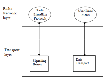
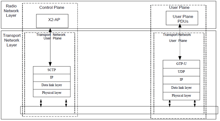
There shall exist a clear separation between the Radio Network Layer and the Transport Layer. Therefore, the radio network signalling and X2 data streams are separated from the data transport resource and traffic handling as shown in Figure 6.1.1.

Figure 6.1.1: Separation of Radio Network Protocols and transport over X2
(⇒ copy of original 3GPP image)
(⇒ copy of original 3GPP image)
6.2 Radio signalling protocols p. 11
6.2.1 X2AP protocol p. 11
The protocol responsible for providing signalling information across the X2 interface is called the X2 Application Protocol (X2AP). The X2AP is terminated by the two eNBs inter-connected via the X2 interface X2AP Procedure Modules.
6.3 User plane protocol p. 11
6.4 X2 interface protocol structure p. 11
The X2 interface protocol architecture consists of two functional layers:
- Radio Network Layer, defines the procedures related to the interaction between eNBs. The radio network layer consists of a Radio Network Control Plane and a Radio Network User Plane.
- The transport network layer provides services for user plane and signalling transport.

7 Other X2 interface specifications p. 12
7.1 E-UTRAN X2 interface: X2 layer 1 (TS 36.421) p. 12
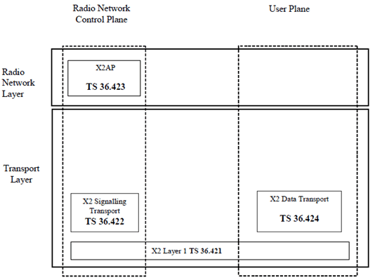
TS 36.421 specifies the range of physical layer technologies that may be used to support the X2 interface.
7.2 E-UTRAN X2 interface: X2 signalling transport (TS 36.422) p. 12
TS 36.422 specifies how the X2AP signalling messages are transported over X2.
7.3 E-UTRAN X2 interface: X2 application protocol (X2AP) (TS 36.423) p. 12
TS 36.423 specifies the radio network layer signalling procedures of the control plane between eNBs in E-UTRAN.
7.4 E-UTRAN X2 interface: X2 data transport (TS 36.424) p. 12
TS 36.424 specifies the standards for user data transport protocols over the E-UTRAN X2 interface.
7.5 Summary of E-UTRAN X2 interface Technical Specifications p. 12
The relationship between the technical specifications that define the E-UTRAN X2 interface is shown in Figure 7.5.1.
