TS 36.410
E-UTRAN – S1 Interface
General Aspects and Principles
V18.0.0 (PDF)
2024/03 17 p.
V17.0.0
2022/03 17 p.
V16.0.0
2020/06 17 p.
V15.0.0
2018/06 17 p.
V14.0.0
2017/03 17 p.
V13.0.0
2015/12 17 p.
V12.1.0
2014/12 17 p.
V11.1.0
2013/09 17 p.
V10.3.0
2012/07 17 p.
V9.1.1
2011/04 17 p.
V8.3.0
2010/06 17 p.
- Rapporteur:
- Mr. Godin, Philippe
Alcatel-Lucent
Content for TS 36.410 Word version: 18.0.0
1 Scope
2 References
3 Definitions and abbreviations
4 General aspects
5 Functions of the S1 interface protocols and functional split
6 S1 interface protocol structure
7 Other S1 interface specifications
$ Change History
1 Scope p. 6
The present document is an introduction to the 3GPP TS 36.41x series of technical specifications that define the S1 interface for the interconnection of the evolved NodeB (eNB) component of the Evolved Universal Terrestrial Radio Access Network (E-UTRAN) to the Core Network (CN) of the Evolved Packet System (EPS).
2 References p. 6
The following documents contain provisions which, through reference in this text, constitute provisions of the present document.
- References are either specific (identified by date of publication, edition number, version number, etc.) or non-specific.
- For a specific reference, subsequent revisions do not apply.
- For a non-specific reference, the latest version applies. In the case of a reference to a 3GPP document (including a GSM document), a non-specific reference implicitly refers to the latest version of that document in the same Release as the present document.
[1]
TR 21.905: "Vocabulary for 3GPP Specifications".
[2]
TS 36.401: "Evolved Universal Terrestrial Radio Access Network (E-UTRAN); Architecture description".
[3]
TS 36.411: "Evolved Universal Terrestrial Radio Access Network (E-UTRAN); S1 layer 1".
[4]
TS 36.412: "Evolved Universal Terrestrial Radio Access Network (E-UTRAN); S1 signalling transport".
[5]
TS 36.413: "Evolved Universal Terrestrial Access (E-UTRA); S1 Application Protocol (S1 AP)".
[6]
TS 36.414: "Evolved Universal Terrestrial Radio Access Network (E-UTRAN); S1 data transport".
[7]
RFC 4960 (2007-09): "Stream Control Transmission Protocol".
[8]
TS 29.281: "General Packet Radio Service (GPRS); GPRS Tunnelling Protocol User Plane (GTPv1-U)".
[9]
TS 23.401: "General Packet Radio Service (GPRS) enhancements for Evolved Universal Terrestrial Radio Access Network (E-UTRAN) access".
[10]
TS 36.455: "Evolved Universal Terrestrial Access (E-UTRA); LTE Positioning Protocol A (LPPa)".
[11]
TS 36.300: "Evolved Universal Terrestrial Radio Access (E-UTRA), Evolved Universal Terrestrial Radio Access Network (E-UTRAN); Overall description; Stage 2".
[12]
TS 33.401: "3GPP System Architecture Evolution (SAE); Security architecture".
3 Definitions and abbreviations p. 6
3.1 Definitions p. 6
For the purposes of the present document, the terms and definitions given in TR 21.905 and the following apply.
A term defined in the present document takes precedence over the definition of the same term, if any, in TR 21.905.
Dual Connectivity:
mode of operation of a UE in RRC_CONNECTED, configured with a Master Cell Group and a Secondary Cell Group as defined in TS 36.300.
E-RAB:
as defined in TS 36.401.
3.2 Abbreviations p. 7
For the purposes of the present document, the abbreviations given in TR 21.905 and the following apply.
An abbreviation defined in the present document takes precedence over the definition of the same abbreviation, if any, in TR 21.905.
AS
Access Stratum
CMAS
Commercial Mobile Alert Service
DC
Dual Connectivity
E-RAB
E-UTRAN Radio Access Bearer
eNB
E-UTRAN Node B
EPC
Evolved Packet Core
EPS
Evolved Packet System
ETWS
Earthquake and Tsunami Warning System
GTP-U
GPRS Tunnelling Protocol
IP
Internet Protocol
LTE
Long Term Evolution
MeNB
Master eNB
MME
Mobility Management Entity
O&M
Operation and Maintenance
PWS
Public Warning System
QoS
Quality of Service
RAT
Radio Access Technology
RIM
RAN Information Management
RNL
Radio Network Layer
S1-U
S1 User plane interface
S1-MME
S1 control plane interface
S-GW
Serving Gateway
S1AP
S1 Application Protocol
SAP
Service Access Point
SCG
Secondary Cell Group
SeNB
Secondary eNB
SCTP
Stream Control Transmission Protocol
TNL
Transport Network Layer
3.3 Specification notations p. 7
For the purposes of the present document, the following notations apply:
Procedure
When referring to a procedure in the specification the Procedure Name is written with the first letters in each word in upper case characters followed by the word "procedure", e.g. Radio Network Layer (RNL) procedures.
Message
When referring to a message in the specification the MESSAGE NAME is written with all letters in upper case characters followed by the word "message", e.g. RADIO LINK SETUP REQUEST message.
4 General aspects p. 7
This clause captures the S1 interface principles and characteristics.
4.1 E-UTRAN architecture p. 8
The E-UTRAN is layered into a Radio Network Layer (RNL) and a Transport Network Layer (TNL). The E-UTRAN architecture, i.e. the E-UTRAN logical nodes and interfaces between them, are defined as part of the RNL.
The E-UTRAN architecture consists of a set of eNBs connected to the EPC through the S1 interface. The overall LTE architecture and E-UTRAN architecture are described in TS 36.401. This subclause specifies only the architecture of the S1 interface, and shall not constrain the network architecture of either core or radio access networks.
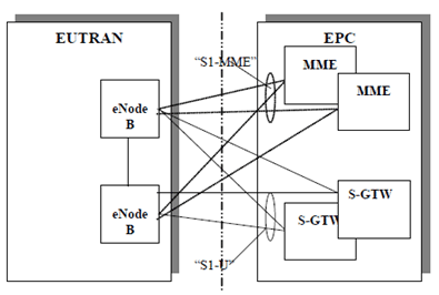
The S1 interface is specified at the boundary between the EPC and the E-UTRAN. Figure 4.1 depicts the logical division of the S1 interface. From the S1 perspective, the E-UTRAN access point is an eNB, and the EPC access point is either the control plane MME logical node or the user plane S-GW logical node. Two types of S1 interfaces are thus defined at the boundary depending on the EPC access point: S1-MME towards an MME and S1-U towards an S- GW.

The E-UTRAN may thus have several S1 access points towards the EPC. As a minimum, each S1 access point
(in E-UTRAN or EPC) shall independently fulfil the requirements of the relevant S1 specifications (3GPP 36.41x series - see clause 7).
S1 is a logical interface.
There may be multiple S1-MME logical interfaces towards the EPC from any one eNB. The selection of the S1-MME interface is then determined by the NAS Node Selection function as described in clause 5.
There may be multiple S1-U logical interfaces towards the EPC from any one eNB. The selection of the S1-U interface is done within the EPC and signalled to the eNB by the MME.
4.2 S1 interface general principles p. 8
The general principles for the specification of the S1 interface are as follows:
- the S1 interface should be open;
- the S1 interface shall support the exchange of signalling information between the eNB and EPC;
- from a logical standpoint, the S1 is a point-to-point interface between an eNB within the E-UTRAN and an MME in the EPC. A point-to-point logical interface should be feasible even in the absence of a physical direct connection between the eNB and MME.
4.3 S1 interface specification objectives p. 9
The S1 interface specification shall facilitate the following:
- inter-connection of eNBs with MMEs supplied by different manufacturers;
- separation of S1 interface Radio Network functionality and Transport Network functionality to facilitate introduction of future technology.
4.4 S1 interface capabilities p. 9
The S1 interface supports:
- procedures to establish, maintain and release E-UTRAN Radio Access Bearers;
- procedures to perform intra-LTE handover and inter-RAT handover;
- the separation of each UE on the protocol level for user specific signalling management;
- the transfer of NAS signalling messages between UE and EPC;
- location services by transferring requests from the EPC to E-UTRAN, and location information from E-UTRAN to EPC;
- mechanisms for resource reservation for packet data streams.
4.5 S1 interface characteristics p. 9
4.5.1 Use of the Stream Control Transmission Protocol (SCTP) p. 9
The SCTP protocol (IETF RFC 4960 [7]) is used to support the exchange of S1 Application Protocol (S1AP) signalling messages between an eNB and an MME.
5 Functions of the S1 interface protocols and functional split p. 9
5.1 General p. 9
The following clauses describe the functions supported over S1-MME and S1-U to fulfil the S1 interface capabilities.
5.2 S1 UE context management function p. 9
In order to support UEs in the LTE_ACTIVE state, UE contexts need to be managed, i.e. established and released in the eNB and in the EPC to support user individual signalling on S1. This includes security context management.
The S1 UE context management function supports the establishment of the necessary overall initial UE context including E-RAB context, security context, roaming and access restrictions, UE S1 signalling connection ID(s), etc. in the eNB to enable fast idle-to-active transition.
The establishment of the overall initial UE context is initiated by the MME.
The S1 UE context management function also supports the release of the context previously established in the eNB to enable the active-to-idle transition. The release of the context is triggered by the MME either directly or following a request received from the eNB.
5.3 E-RAB management functions p. 10
The E-RAB service management function is responsible for establishing, modifying and releasing E-UTRAN resources for user data transport once a UE context is available in the eNB. The establishment and modification of E-UTRAN resources is triggered by the MME and requires respective QoS information to be provided to the eNB. For Dual Connectivity when SCG bearer option is applied, the modification of the E-RAB is triggered by the MeNB towards the MME for the modification of the transport information. The release of E-UTRAN resources is triggered by the MME either directly or following a request received from the eNB (optional).
5.4 S1 link management function p. 10
5.4.1 GTP-U tunnels management function p. 10
This function is used to establish and release GTP-U (TS 29.281) tunnels between the EPC and the
E-UTRAN upon an E-RAB service request. This involves assigning a tunnel identifier for each direction.
5.4.2 S1 signalling link management function p. 10
The S1 signalling link management function provides a reliable transfer of the radio network signalling between
E-UTRAN and EPC.
5.5 Mobility functions for UEs in LTE_Active p. 10
5.5.1 Intra-LTE handover p. 10
The Intra-LTE handover function supports mobility for UEs in LTE_ACTIVE and comprises the preparation, execution and completion of handover via the X2 and S1 interfaces.
5.5.2 Inter-3GPP RAT handover p. 10
The Inter-3GPP-RAT handover function supports mobility to and from other 3GPP-RATs for UEs in LTE_ACTIVE and comprises the preparation, execution and completion of handover via the S1 interface.
5.5.3 Mobility to CDMA2000 system p. 10
The mobility to non-3GPP radio system function supports mobility to and from other non-3GPP radio technologies for UEs in LTE_ACTIVE, namely to and from CDMA2000 systems. This comprises signalling for pre-registration of UE with CDMA2000 HRPD network and signalling for handover preparation for handover from E-UTRAN to CDMA2000 HRPD/1xRTT.
5.6 Paging function p. 10
The paging function supports the sending of paging requests to the eNBs having one or more cells which correspond to one of the TAs in which the UE is registered.
5.7 Void
5.7a Roaming and access restriction support functions p. 10
The S1 interface supports the transfer of roaming and access restriction information from the EPC to the eNB for the UE in the network.
5.8 S1 interface management function p. 11
The error indication function is used by the eNB (respectively the MME) to indicate to the MME (respectively the eNB) that a logical error has occurred.
The reset function is used to initialize the peer entity after node setup and after a failure event occurred. This procedure can be used by both the eNB and MME.
The S1 setup (respectively the eNB and MME configuration update) function allows to exchange (respectively update) application level data needed for the eNB and MME to interoperate correctly on the S1 interface.
5.9 Coordination functions p. 11
5.9.1 Network sharing function p. 11
The S1 interface supports the transfer of the UE's serving PLMN and of equivalent PLMNs to the serving PLMN.
5.9.2 NAS node selection function p. 11
The interconnection of eNBs to multiple MME / S-GWs is supported by the LTE/EPS architecture (see TS 23.401 and TS 36.300). Therefore a NAS node selection function is located in the eNB to determine the MME association of the UE.
This functionality is located in the eNB to determine and establish an association between a given UE and one of the MME nodes that comprise the pool area the eNB belongs to.
It then enables proper routeing via the S1-MME interface.
On S1, no specific procedure corresponds to the NAS node selection function.
The S1 interface supports the indication by the MME of its relative capacity to the eNB, in order to achieve load-balanced MMEs within the pool area.
When the eNB is configured to ensure that the selected MME serves the country where the UE is located, as described in TS 23.401, the eNB takes into account UE location information, if available, when determining the MME.
5.9.3 MME overload control function p. 11
The S1 interface supports the indication by the MME of its overload situations to the eNB.
5.10 Security function p. 11
5.10.1 Data confidentiality p. 11
5.10.1.1 Radio interface ciphering function p. 11
The radio interface may be ciphered. Both, signalling and user data, may be subject to ciphering. The ciphering shall be done within the E-UTRAN.
5.10.1.2 Ciphering key management function p. 11
5.10.2 Data integrity p. 12
5.10.2.1 Integrity checking p. 12
The purpose of the integrity check is to ensure the integrity of the signalling messages over the air interface to make sure that the signalling continues between the same elements, i.e., the UE and the eNB that first established the secure connection. The integrity check shall be done within the E-UTRAN.
5.10.2.2 Integrity key management p. 12
5.11 Service and network access function p. 12
5.11.1 Core network signalling data transfer function p. 12
The NAS EPC signalling data shall be transparently conveyed between the EPC and the UE. Over the S1 interface, the same S1 interface channel that is used for the E-UTRAN-EPC signalling shall be used.
5.11.2 UE tracing p. 12
This function allows tracing of various events related to the UE and its activities. This is an O&M functionality.
5.11.3 Location reporting function p. 12
The positioning function performs the determination of the geographical position of the UE.
This function allows the MME to request the eNB for a given UE either to report directly the current serving cell or to report upon change of serving cell.
If dual connectivity is configured for a specific UE, the location reported refers to the cell served by the MeNB.
5.11.4 LTE Positioning Protocol A (LPPa) signalling transfer function p. 12
The LPPa (TS 36.455) signalling data is transparently conveyed between the E-SMLC and the eNB.
5.11.5 Delivery of warning messages p. 12
This function provides the capability to start or stop the delivery of warning notification messages related to alerts (earthquake, tsunami, etc..). The messages belong to one of the independent warning services: ETWS, CMAS or the other services which use the same Access Stratum (AS) mechanisms as CMAS as described in TS 36.300.
In ETWS, the messages to be delivered can either be primary notifications which have stringent delivery delay or secondary notifications.
5.12 RAN Information Management (RIM) function p. 12
The RAN Information Management (RIM) function is a generic mechanism that allows the request and transfer of information (e.g. GERAN/UTRAN system information) between two RAN nodes via the Core Network (CN).
5.13 Configuration Transfer function p. 12
The Configuration Transfer function allows the request and transfer of RAN configuration information (e.g., SON information) between two RAN nodes via the Core Network (CN).
6 S1 interface protocol structure p. 13
The protocol structure is following the structure defined in TS 36.401.
6.1 General p. 13
The radio network signalling over S1consists of the S1 Application Part (S1AP). The S1AP protocol consists of mechanisms to handle all procedures between the EPC and E-UTRAN. It is also capable of conveying messages transparently between the EPC and the UE without interpretation or processing by the E-UTRAN.
Over the S1 interface the S1AP protocol is, e.g., used to:
- Facilitate a set of general E-UTRAN procedures from the EPC such as paging-notification as defined by the notification Service Access Point (SAP).
- Separate each User Equipment (UE) on the protocol level for mobile specific signalling management as defined by the dedicated SAP.
- Transfer of transparent non-access signalling as defined in the dedicated SAP.
- Request of various types of E-RABs through the dedicated SAP.
- Perform the mobility function.
6.2 S1-MME p. 13
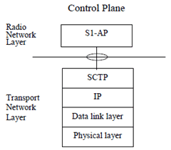
Figure 6.2-1 shows the protocol structure for S1-MME, following the structure described in TS 36.401.

The Transport Network Layer (TNL) is based on IP transport, comprising the Stream Control Transmission Protocol (SCTP) on top of IP.
6.3 S1-U p. 14
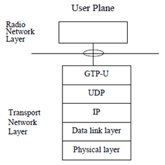
Figure 6.3-1 shows the protocol structure for S1-U, following the structure described in TS 36.401.

7 Other S1 interface specifications p. 14
This clause contains the description of the other related 3GPP specifications.
7.1 E-UTRAN S1 interface: layer 1 (3GPP TS 36.411) p. 14
3GPP TS 36.411 specifies the physical layer technologies that may be used to support the S1 interface.
7.2 E-UTRAN S1 interface: signalling transport (3GPP TS 36.412) p. 14
3GPP TS 36.412 specifies the signalling bearers for the S1AP for the S1-MME interface.
7.3 E-UTRAN S1 interface: S1AP specification (3GPP TS 36.413) p. 14
3GPP TS 36.413 specifies the S1AP protocol for radio network control plane signalling over the S1 interface.
7.4 E-UTRAN S1 interface: data transport and transport signalling (3GPP TS 36.414) p. 14
3GPP TS 36.414 specifies the transport bearers for the user plane of the S1-U interface.