Content for TS 32.240 Word version: 19.0.0
F Distributed deployment models
F.1 General
F.2 High level deployment models
F.2.1 Centralized CHF deployment
F.2.2 Local/Edge CHF deployment
F Distributed deployment models |R18| p. 68
F.1 General p. 68
This Annex provides information that the charging functions can be deployed in multiple physical locations.
This Annex provides an overview of the distributed deployment options for CHF, which may be based on two deployment models: Centralized Deployment Model and Local/Edge Deployment Model. Either one or a combination of the two deployment models may be used.
It will focus on the possibility of deploying different CHF instances, and respective charging functions in different physical locations. Nevertheless, the current specification only considers when CHF, ABMF, and RF are located together. This Annex can be used to support the design of Charging Architecture in 5GS.
F.2 High level deployment models p. 68
F.2.1 Centralized CHF deployment p. 68
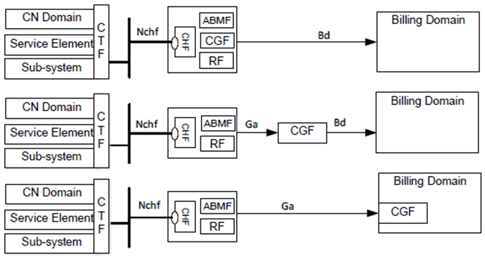
The architecture options depicted in Figure F.2.1-1 provides an overview of the deployment architecture where all CCS components are available in the same physical location, i.e. the CHF is located at the central location. On this case, the NF consumer (e.g. SMF) generates the charging events through CTF towards the CHF either for a converged or offline charging scenario. The message flow and CHF selection method are detailed in the respective middle tier specifications, e.g. in TS 32.255.

Figure F.2.1-1: Converged charging architecture --- central deployment
(⇒ copy of original 3GPP image)
(⇒ copy of original 3GPP image)
F.2.2 Local/Edge CHF deployment p. 68
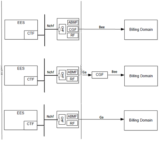
There is an option of distributing CCS functions in a distributed way by making available, e.g. in Figure F.2.2-1, a CHF instance and the Edge Enablement Server (EES) is located in the same Service Deployment Cluster. On this case the CHF instance selected may be the one physically closer to the EES. Therefore, the charging events would be generated through the CTF towards the CHF that is available at the Local/Edge, e.g. in clause 4.2.3 of TS 32.257. Furthermore, there are other distributed models that can be used, for instance, the availability of NF(CTF), instead of using an EES, in the Service Deployment Cluster.

Figure F.2.2-1: Converged charging architecture --- distributed deployment
(⇒ copy of original 3GPP image)
(⇒ copy of original 3GPP image)