Content for TS 32.101 Word version: 18.0.0
7 PLMN management functional architecture
7.1 TM architectural aspects
7.2 Performance Management
7.3 Roaming management overview
7.4 Fraud management overview
7.5 Fault Management
7.6 Security Management
...
...
7 PLMN management functional architecture p. 38
7.1 TM architectural aspects p. 38
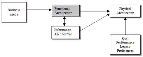
The basic aspects of a TM architecture, which can be, considered when planning and designing a TM are:
- the functional architecture;
- the information architecture;
- the physical architecture.

All management processes have functions in several management areas. By identifying only those processes and interfaces relating to a certain management function, for example performance management, it is possible to take a slice through the Enhanced Telecom Operations Map that details the functional architecture for performance management, this will be the approach taken by the present document.
The management functions are:
- Performance management;
- Roaming management;
- Fraud management;
- Fault management;
- Security management;
- Software management
- Configuration management;
- Accounting management;
- Subscription management;
- Quality of Service (QoS) management (see informative Annex D);
- User equipment management.
7.2 Performance Management p. 39
7.2.1 Overview |R4| p. 39
An initial view of Performance Management is described in [105]. This shows an example decomposition of Performance Management processes to identify essential information flows. It shows a slice through the Telecom Operations Map from a Performance Management point of view. This slice is applicable to Mobile Networks and other networks. Although the "slice" or view is quite large, it does not contain all interfaces or process activities that are related to Performance Management. It does however show the main processes and interfaces involved in Performance Management. Please refer to [105] for further detail.
7.2.2 Standardisation objectives |R4| p. 39
During the lifetime of a 3GPP system, its logical and physical configuration will undergo changes of varying degrees and frequencies in order to optimise the utilisation of the network resources. These changes will be executed through network configuration management activities and/or network engineering, see TS 32.600.
Many of the activities involved in the daily operation and future network planning of a 3GPP system require data on which to base decisions. This data refers to the load carried by the network and the grade of service offered. In order to produce this data performance measurements are executed in the NEs, which comprise the network. The data can then be transferred to an external system, e.g. an Operations System (OS) in TMN terminology, for further evaluation. The purpose of the present document is to describe the mechanisms involved in the collection of the data and the definition of the data itself.
The Performance Management functional area concerns the management of performance measurements and the collection of performance measurement data across a 3GPP system. It defines the administration of measurement schedules by the Network Element Manager (EM), the generation of measurement results in the Network Elements (NEs) and the transfer of these results to one or more Operations Systems, i.e. EM(s) and/or Network Manager(s) (NM(s)).
The management requirements have been derived from existing telecommunications operations experience. The management definitions were then derived from other standardisation work so as to minimise the re-invention factor. References are given as appropriate.
The objectives of the present document are:
- To provide the descriptions for a standard set of measurements;
- To produce a common description of the management technique for measurement administration and result accumulation; and
- To define a method for the bulk transmission of measurement results across a management interface.
7.3 Roaming management overview p. 40
Roaming is a service provided by Mobile Service Providers. Customers of a Home Service Provider may use the infrastructure of another, a Serving Service Provider (see Figure 7.3-1) to give its customer the ability to make calls when outside the home service provider's territory. The goal is to have a customer receive the same service (or as close to the same service) when travelling in an area supported by another network as the customer receives when in their home service provider's area. Please refer to [105] to see an example implementation with more detail.

Figure 7.3-1: Relationships between Subscriber, Home and Serving Service Provider
(⇒ copy of original 3GPP image)
(⇒ copy of original 3GPP image)
7.4 Fraud management overview p. 40
Fraud and all the activities to detect and prevent fraud are quite common to any network. Nonetheless, mobility and roaming, two integral mobile services, make fraud detection and fraud prevention more complicated and more urgent. The mobile service provider does not know the location of the "end of the wire," which would lead to the home of a fraudulent customer. For roaming, the situation is demonstrably worse. For a roaming visitor the caller is not the service provider's customer and therefore, the service provider does not have complete information to assess fraud. In the reverse case, the service provider has little control when its customers are roaming, e.g., potentially going over credit limits or using service after being suspended. In this case, the fraudulent customer uses the network facilities of another provider (the serving service provider) meaning the home service provider has to rely on the serving service provider for some level of fraud protection support. This means to a large extent that fraud prevention is largely out of the control of the home service provider when one of its customers roams on another network and out of the control of a serving service provider when being visited by another provider's roamer. Please refer to [105] to see an example implementation with more detail.
7.5 Fault Management p. 41
7.5.1 Overview |R4| p. 41
Fault Management is accomplished by means of several processes/sub-processes like fault detection, fault localisation, fault reporting, fault correction, fault repair, etc. These processes/sub-processes are located over different management layers, however, most of them (like fault detection, fault correction, fault localisation and fault correction) are mainly located over the Network Element and Network Element Management layers, since this underlying network infrastructure has the 'self healing' capabilities.
It is possible, however, that some faults/problems affecting the telecom services are detected within the "Network and Systems Management" layer, by correlating the alarm/events (originated by different Network Elements) and correlating network data, through network data management.
Network data management logically collects and processes performance and traffic data, as well as usage data.
While the Fault Management triggered within the Network Element and NE management layers is primarily reactive, the Fault Management triggered within the Network and Systems Management layer is primarily proactive. Meaning triggered by automation rather than triggered by the customer; and this is important for improving service quality, customer perception of service and for lowering costs.
Focusing on the Network and Systems Management layer, when a fault/problem is detected, no matter where and how, several processes are implicated, as described in Figure 6.
Figure 6 taken from the Telecom Operations Map [100] shows an example of how Fault Management data can be used to drive an operator's service assurance process. Service assurance then becomes primarily proactive, i.e. triggered by automation rather than triggered by the customer. It is argued that this approach is crucial to improving service quality, customer perception of service and for lowering costs.
![Copy of original 3GPP image for 3GPP TS 32.101, Fig. 6: Service Assurance Process Flow (* imported from [100])](../img/tinv-32-101-6.gif)
TOM assurance activities (and their associated interfaces) shown in Figure 6 can be associated with ITU-T TMN service components from TS 32.111-series [3] according to Table 1:
| ITU-T TMN Service Component
TS 32.111-x [3] |
TOM Network Management Assurance Activities |
|---|---|
| Alarm Surveillance | Detect Fault |
| Fault Localisation | Isolate Root Cause |
| Fault Correction | Decide Repair / Allocate Resources |
| Testing | Test |
The TOM assurance example shown in Figure 6 also recognises that Performance Management data can also be used to detect network problems.
The TOM assurance example also adds some detail to the Service Management Layer by showing how activities such as determining and monitoring Service Level Agreements (SLAs) and trouble ticket reporting are interfaced to the Network Management layer.
7.5.2 Standardisation objectives |R4| p. 42
A 3GPP system is composed of a multitude of Network Elements (NE) of various types and, typically, different vendors, which inter-operate in a co-ordinated manner in order to satisfy the network users' communication requirements.
The occurrence of failures in a NE may cause a deterioration of this NE's function and/or service quality and will, in severe cases, lead to the complete unavailability of the respective NE. In order to minimise the effects of such failures on the Quality of Service (QoS) as perceived by the network users it is necessary to:
- detect failures in the network as soon as they occur and alert the operating personnel as fast as possible;
- isolate the failures (autonomously or through operator intervention), i.e. switch off faulty units and, if applicable, limit the effect of the failure as much as possible by reconfiguration of the faulty NE/adjacent NEs;
- if necessary, determine the cause of the failure using diagnosis and test routines; and
- repair/eliminate failures in due time through the application of maintenance procedures.
7.6 Security Management p. 43
7.6.1 Overview |R4| p. 43
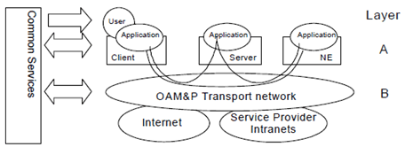
This clause describes an architecture for security management of the TMN that is divided into two layers, as shown in Figure 7. No individual layer is dependent on any specific technology in the other one.

7.6.1.1 Layer B - OAM&P Transport IP Network p. 43
Some Service Providers might build their OAM&P transport network as a completely private, trusted network. In the normal case though, the OAM&P transport network should be regarded as partly insecure due to its size, complexity, limited physical security and possible remote access from dial-up connections or from the Internet. The only security service provided then is that the OAM&P transport network when based on IP is logically separated from the Internet. For IP based transports infrastructure aspects on security are handled to the extent possible utilizing IP classic features (addressing schemes, DNS, DHCP, BOOTP, protection with firewalls etc.).
Additionally, a trusted IP-environment to the application level might be provided, e.g. an environment with no masquerading IP-hosts and where potential intruders cannot communicate. One way to accomplish such a secure DCN is to use IP security mechanisms (IPSec; see RFC 2401 [7]) to achieve authentication of IP hosts (servers, gateways, Network Elements) and optional encryption of OAM&P traffic. Note however that the secure DCN does not authenticate users.
7.6.1.2 Layer A - Application Layer p. 43
On this layer we find Telecom Management applications performing their tasks in the normal management functional areas. Managed objects residing in the network resources are often accessed or manipulated.
Layer A provides authentication of users ensuring that every party involved in OAM&P traffic is securely authenticated against every other party. The implementation of the authentication service supports "single log-on" (a user only has to log-on once to get access to all OAM&P applications in the network) and "single point of administration" (an administrator only needs to maintain a user and his/her profile in one place).
Layer A also provides authorization (access control) - to verify if a user is authorized to perform a certain operation upon a specified target object at a given time. In addition, it addresses the use of signing and logging of events. Logging of events here means "logging of actions" (not necessarily logging of ALL actions) to be able to check "who did what". At least all "critical" actions (configurations etc.) should be logged.
Interface definitions addressing authentication and authorization are needed. Also note that layer A requires confidentiality. Layer B may provide this service. If not, layer A instead has to provide it itself.
7.6.1.3 Common Services p. 44
In common services we find the security infrastructure components:
- Directory (for storage of user information, certificates, etc.);
- PKI (Certificate Authority, Registration Authority, Public Key Certificate, etc.).