Content for TR 26.998 Word version: 18.1.0
0…
4…
4.2…
4.2.2…
4.2.2.2
4.2.2.3
4.2.2.4
4.2.3…
4.3…
4.4…
4.5…
4.6…
4.6.4…
4.6.5…
4.6.8…
5
6…
6.2…
6.2.4…
6.2.4.2
6.2.5…
6.3…
6.3.4…
6.3.4.2
6.3.5…
6.4…
6.4.4
6.4.5…
6.5…
6.5.4
6.5.5
6.5.6…
6.6…
6.6.4
6.6.5…
7…
8…
8.9
9
A…
A.2
A.3…
A.4
A.5
A.6
A.7…
4.3 Basic Processes for delivering an AR experience
4.3.1 Introduction
4.3.2 AR Media Delivery Pipeline
4.3.3 XR Spatial Compute Pipeline
...
...
4.3 Basic Processes for delivering an AR experience p. 25
4.3.1 Introduction p. 25
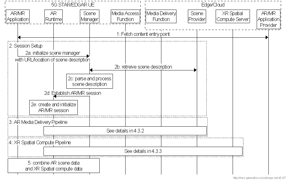
In this clause we provide a typical workflow for setting up a session between a 5G UE and network/cloud for receiving AR scenes from a scene provider. The basic workflow is provided in Figure 4.3.1-1. In this case, the following steps happen:
Step 1.
The application contacts the application provider to fetch the entry point for the content. The acquisition of the entry point may be performed in different ways and is considered out of scope. An entry point may for example be a URL to a scene description.
Step 2.
Session set up:
Step 3.
- In case when the entry point is a URL of a scene description, the application initializes the Scene Manager using the acquired entry point.
- The Scene Manager retrieves the scene description from the scene provider based on the entry point information.
- The Scene Manager parses the entry point and creates the immersive scene.
- The Scene Manager requests the creation of a local AR/MR session from the AR Runtime.
- The AR Runtime creates a local AR/MR session and performs registration with the local environment. Then steps 3 and 4 run in parallel:
AR Media Delivery Pipeline: In case when entry point is a scene URL, a delivery session - for accessing scenes (new scenes or scene updates) and related media over the network is established. This can basically use the MAF as well as the scene manager and the corresponding network functions. Details are introduced in clause 4.3.2.
Step 4.
XR Spatial Compute Pipeline: A pipeline that uses sensor data to provide an understanding of the physical space surrounding the device to determine the device's position and orientation and placement of AR objects in reference to the real world and uses XR Spatial Description information from the network to support this process. This uses the XR Spatial Description functions as introduced in clause 4.4.7. Details are introduced in clause 4.3.3.
Step 5.
Steps 3 and 4 run independently, but the results of both pipelines (e.g., media organized in a scene graph and pose of the AR device) are inputs of the AR/MR Scene Manager function. This function handles the common processing of the two asynchronous pipelines to create an AR experience.

4.3.2 AR Media Delivery Pipeline p. 27
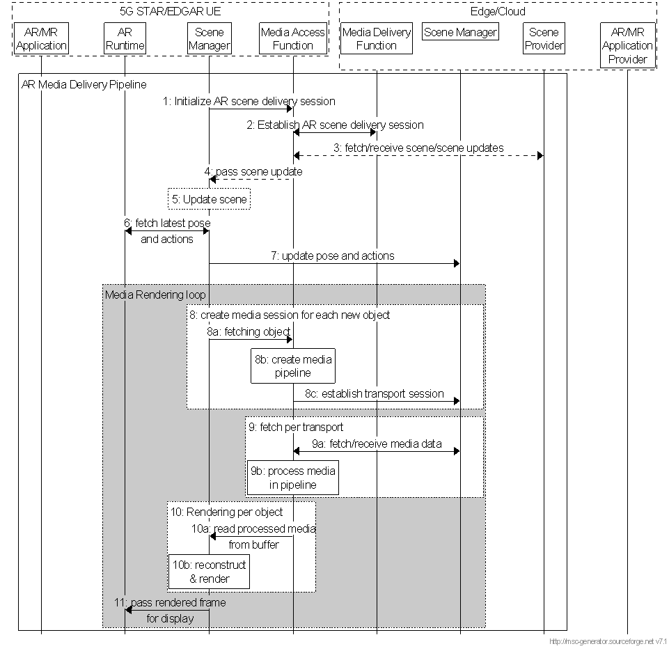
In this clause, we provide the detailed processes to set up AR Media Delivery Pipeline as addressed in step 3 of Figure 4.3.1-1. This generic basic process may be extended to address specific applications and use cases. The call flow as shown in Figure 4.3.2-1 aligns with the STAR/EDGAR architecture and serves as a baseline for defining use-case specific call flows.

For an AR Media Delivery Pipeline:
Step 1.
The Scene Manager initializes AR delivery session.
Step 2.
The MAF establishes AR delivery session.
Step 3.
The MAF may receive updates to the scene description from the scene provider
Step 4.
The MAF passes the scene update to the Scene Manager.
Step 5.
The Scene Manager updates the current scene.
Step 6.
The Scene Manager acquires the latest pose information and the user's actions
Step 7.
The Scene Manager in the device shares that information with the Scene Manager in edge/cloud
The media rendering loop consists of the following steps. Note that steps 8, 9 and 10 are running as 3 parallel loops:
Step 8.
For each new object in the scene:
Step 9.
- The Scene Manager triggers the MAF to fetch the related media.
- The MAF creates a dedicated media pipeline to process the input.
- The MAF establishes a transport session for each component of the media object.
For each transport session:
Step 10.
- The media pipeline fetches the media data. It could be static, segmented, or real-time media streams.
- The media pipeline processes the media and makes it available in buffers.
For each object to be rendered:
Step 11.
- The Scene Manager gets processed media data from the media pipeline buffers
- The Scene Manager reconstructs and renders the object
The Scene Manager passes the rendered frame to the AR/MR Runtime for display on the user's HMD.
4.3.3 XR Spatial Compute Pipeline p. 28
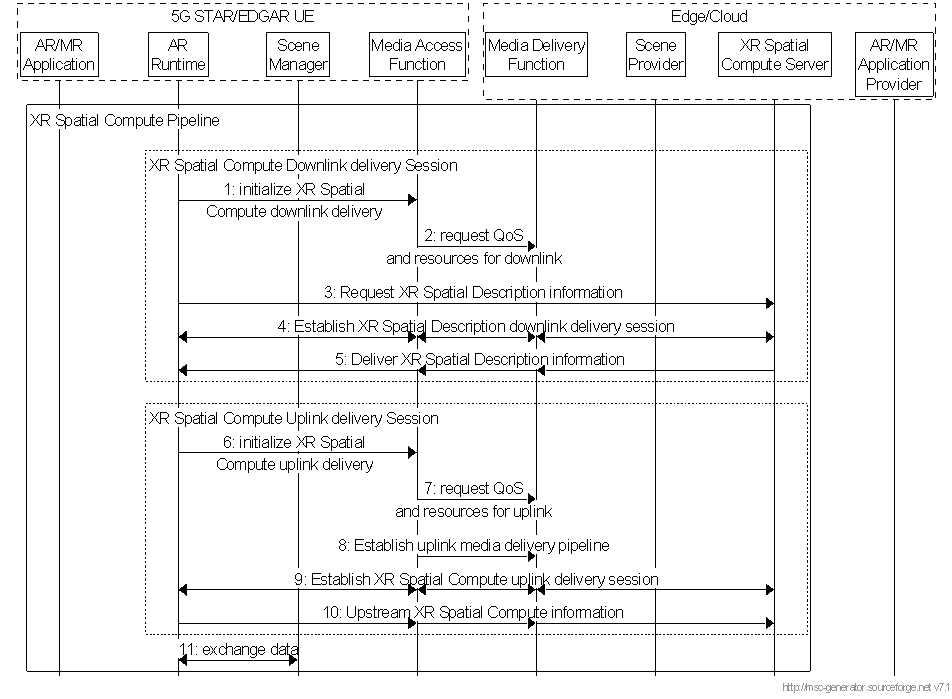
In this clause, we provide the detailed processes to set up an XR Spatial Compute Pipeline for spatial description related data as addressed in step 4 of Figure 4.3.1-1. This generic basic process may be extended to address specific applications and use cases. The call flow as shown in Figure 4.3.3-1 aligns with the STAR/EDGAR architecture and serves as a baseline for defining use-case specific call flows.

For a XR Spatial Compute downlink delivery session:
Step 1.
For a XR Spatial Compute uplink delivery session:
The XR Spatial Compute function in the AR Runtime asks the MAF to establish a XR Spatial Compute downlink delivery session
Step 2.
The MAF communicates with the network to establish the proper resources and QoS
Step 3.
The XR Spatial Compute function requests access to XR Spatial Description information
Step 4.
An XR Spatial Description downlink delivery session is established across the XR Spatial Compute server, the media delivery function, the media access function and XR Spatial Compute function on the device.
Step 5.
XR Spatial Description information is delivered in this downlink delivery session
Step 6.
The XR Spatial Compute function in the AR Runtime asks the MAF to establish a XR Spatial Compute uplink delivery session
Step 7.
The MAF communicates with the network to establish the proper resources and QoS
Step 8.
The MAF established an appropriate uplink delivery pipeline
Step 9.
An XR Spatial Description uplink delivery session is established across the XR Spatial Compute function on the device, the media access function, the media delivery function and the XR Spatial Compute server.
Step 10.
Spatial compute information is upstreamed to the XR Spatial Compute server.
Step 11.
Data is continuously exchanged between the Scene Manager and the AR Runtime