Content for TS 26.118 Word version: 18.0.0
A Content Generation Guidelines
A.1 Introduction
A.2 Video
A.2.1 Overview
A.2.2 Decoded Texture Signal Constraints
A.2.2.1 General
A.2.2.2 Constraints for Main and Flexible H.265/HEVC Operation Point
A.2.2.2a Constraints for Main 8K H.265/HEVC Operation Point
A.2.3 Conversion of ERP Signals to CMP
A.2.3.1 General
A.2.3.2 Equirectangular Projection (ERP)
A.2.3.3 Cubemap Projection (CMP)
A.2.3.4 Conversion between two projection formats
...
...
A Content Generation Guidelines p. 72
A.1 Introduction p. 72
This clause collects information that supports the generation of VR Content following the details in the present document. Video and audio related aspects are collected. For additional details and background also refer to TR 26.918.
A.2 Video p. 72
A.2.1 Overview p. 72
This clause collects information on that support the generation of video bitstreams that conform to operation points and media profile in the present document.
A.2.2 Decoded Texture Signal Constraints p. 72
A.2.2.1 General p. 72
Due to the restrictions to use a single decoder, the decoded texture signals require to follow the profile and level constraints of the decoder. Generally, this requires a careful balance of the permitted frame rates, stereo modes, spatial resolutions, and usage of region wise packing for different resolutions and coverage restrictions. Details on preferred settings such as frame rates and spatial resolutions are for example discussed in TR 26.918.
This clause provides a summary of restrictions for the different operation points defined in the present document.
A.2.2.2 Constraints for Main and Flexible H.265/HEVC Operation Point p. 72
The profile and level constraints of H.265/HEVC Main-10 Profile Main Tier Profile Level 5.1 require careful balance of the permitted frame rates, stereo modes, spatial resolutions, and usage of region wise packing for different resolutions and coverage restrictions. If the decoded texture signal is beyond the Profile and Level constraints, then a careful adaptation of the signal is recommended to fulfil the constraints.
This clause provides a brief overview of potential signal constraints and possible adjustments.
Table A.2-1 provides selected permitted combinations of spatial resolutions, frame rates and stereo modes assuming full coverage and no region-wise packing applied. Note that fractional frame rates are excluded for better readability. Note that the Main H.265/HEVC Operation Point only allows frame rates up to 60 Hz.
| Spatial resolution per eye | Stereo | Permitted Frame Rates in Hz |
|---|---|---|
| 4096 × 2048 | None | 24; 25; 30; 50; 60 |
| 3840 × 1920 | None | 24; 25; 30; 50; 60 |
| 3072 × 1536 | None | 24; 25; 30; 50; 60; 90; 100 |
| 2880 × 1440 | None | 24; 25; 30; 50; 60; 90; 100; 120 |
| 2048 × 1024 | None | 24; 25; 30; 50; 60; 90; 100; 120 |
| 2880 × 1440 | TaB | 24; 25; 30; 50; 60 |
| 2048 × 1024 | TaB | 24; 25; 30; 50; 60; 90; 100; 120 |
Table A.2-2 provides the maximum percentage of high-resolution area that can be encoded assuming that the low-resolution area is encoded in 2k resolution covering the full 360 degree area, i.e. using 2048 × 1024 or 1920 × 960 and full coverage is provided for different frame rates. Note also that a viewport typically covers about 12-25% of a full 360 video. Note that fractional frame rates are excluded for better readability.
| Spatial resolution per eye in VP | Spatial resolution per eye in non-VP | Stereo | Frame Rates in Hz | |||||||
|---|---|---|---|---|---|---|---|---|---|---|
| 24 | 25 | 30 | 50 | 60 | 90 | 100 | 120 | |||
| 6144 × 3072 | 2048 × 1024 | None | 9.29% | 9.29% | 9.29% | 9.29% | 9.29% | 5.24% | 4.43% | 3.21% |
| 4096 × 2048 | 2048 × 1024 | None | 21.67% | 21.67% | 21.67% | 21.67% | 21.67% | 12.22% | 10.33% | 7.50% |
| 3840 × 1920 | 1920 × 960 | None | 100.00% | 100.00% | 100.00% | 100.00% | 100.00% | 74.12% | 63.38% | 47.26% |
| 6144 × 3072 | 2048 × 1024 | TaB | 3.21% | 3.21% | 3.21% | 3.21% | 3.21% | 1.19% | 0.79% | 0.18% |
| 4096 × 2048 | 2048 × 1024 | TaB | 7.50% | 7.50% | 7.50% | 7.50% | 7.50% | 2.78% | 1.83% | 0.42% |
| 3840 × 1920 | 1920 × 960 | TaB | 47.26% | 47.26% | 47.26% | 47.26% | 47.26% | 20.40% | 15.02% | 6.96% |
Table A.2-3 provides the maximum percentage of coverage area that can be encoded assuming that the remaining pixels are not encoded for different frame rates. Note that fractional frame rates are excluded for better readability.
| Spatial resolution per eye | Stereo | Frame Rates in Hz | |||||||
|---|---|---|---|---|---|---|---|---|---|
| 24 | 25 | 30 | 50 | 60 | 90 | 100 | 120 | ||
| 6144 × 3072 | None | 47.22% | 47.22% | 47.22% | 47.22% | 47.22% | 31.48% | 28.33% | 23.61% |
| 4096 × 2048 | None | 100.00% | 100.00% | 100.00% | 100.00% | 100.00% | 70.83% | 63.75% | 53.13% |
| 3840 × 1920 | None | 100.00% | 100.00% | 100.00% | 100.00% | 100.00% | 80.59% | 72.53% | 60.44% |
| 6144 × 3072 | TaB | 23.61% | 23.61% | 23.61% | 23.61% | 23.61% | 15.74% | 14.71% | 11.81% |
| 4096 × 2048 | TaB | 53.13% | 53.13% | 53.13% | 53.13% | 53.13% | 35.42% | 31.88% | 26.56% |
| 3840 × 1920 | TaB | 60.44% | 60.44% | 60.44% | 60.44% | 60.44% | 40.30% | 36.27% | 30.22% |
A.2.2.2a Constraints for Main 8K H.265/HEVC Operation Point |R17| p. 73
The profile and level constraints of H.265/HEVC Main-10 Profile Main Tier Profile Level 6.1 require careful balance of the permitted frame rates, stereo modes, spatial resolutions, and usage of region wise packing for different resolutions and coverage restrictions. If the decoded texture signal is beyond the Profile and Level constraints, then a careful adaptation of the signal is recommended to fulfil the constraints.
This clause provides a brief overview of potential signal constraints and possible adjustments.
Table A.2a-1 provides selected permitted combinations of spatial resolutions, frame rates and stereo modes assuming full coverage and no region-wise packing applied. Note that fractional frame rates are excluded for better readability. Note that the Main 8K H.265/HEVC Operation Point only allows frame rates up to 60 Hz.
| Spatial resolution per eye | Stereo | Permitted Frame Rates in Hz |
|---|---|---|
| 8192 × 4096 | None | 24; 25; 30; 50; 60 |
| 7680 × 3840 | None | 24; 25; 30; 50; 60 |
| 6144 × 3072 | None | 24; 25; 30; 50; 60; 90; 100 |
| 5760 × 2880 | None | 24; 25; 30; 50; 60; 90; 100; 120 |
| 4096 × 2048 | None | 24; 25; 30; 50; 60; 90; 100; 120 |
| 5760 × 2880 | TaB | 24; 25; 30; 50; 60 |
| 4096 × 2048 | TaB | 24; 25; 30; 50; 60; 90; 100; 120 |
Table A.2a-2 provides the maximum percentage of coverage area that can be encoded assuming that the remaining pixels are not encoded for different frame rates. Note that fractional frame rates are excluded for better readability.
| Spatial resolution per eye | Stereo | Frame Rates in Hz | |||||||
|---|---|---|---|---|---|---|---|---|---|
| 24 | 25 | 30 | 50 | 60 | 90 | 100 | 120 | ||
| 12288 × 6144 | None | 47.22% | 47.22% | 47.22% | 47.22% | 47.22% | 31.48% | 28.33% | 23.61% |
| 8192 × 4096 | None | 100.00% | 100.00% | 100.00% | 100.00% | 100.00% | 70.83% | 63.75% | 53.13% |
| 7680 × 3840 | None | 100.00% | 100.00% | 100.00% | 100.00% | 100.00% | 80.59% | 72.53% | 60.44% |
| 12288 × 6144 | TaB | 23.61% | 23.61% | 23.61% | 23.61% | 23.61% | 15.74% | 14.71% | 11.81% |
| 8192 × 4096 | TaB | 53.13% | 53.13% | 53.13% | 53.13% | 53.13% | 35.42% | 31.88% | 26.56% |
| 7680 × 3840 | TaB | 60.44% | 60.44% | 60.44% | 60.44% | 60.44% | 40.30% | 36.27% | 30.22% |
A.2.3 Conversion of ERP Signals to CMP p. 74
A.2.3.1 General p. 74
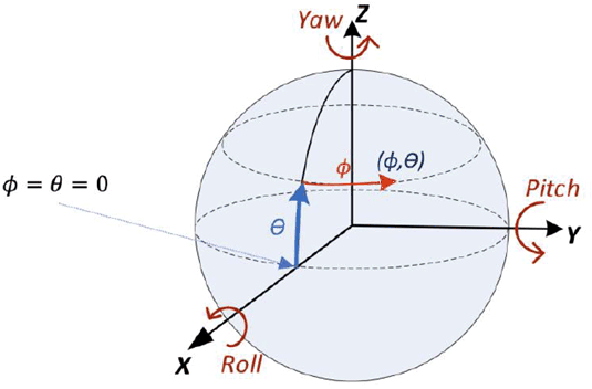
The 3D XYZ coordinate system as shown in Figure A.1 can be used to describe the 3D geometry of ERP and CMP projection format representations. Starting from the center of the sphere, X axis points toward the front of the sphere, Z axis points toward the top of the sphere, and Y axis points toward the left of the sphere.

The coordinate system is specified for defining the sphere coordinates azimuth (Φ) and elevation (θ) for identifying a location of a point on the unit sphere. The azimuth Φ is in the range [−ϖ, ϖ], and elevation θ is in the range [−ϖ/2, ϖ/2], where ϖ is the ratio of a circle's circumference to its diameter. The azimuth (Φ) is defined by the angle starting from X axis in counter-clockwise direction as shown in Figure A.1. The elevation (θ) is defined by the angle from the equator toward Z axis as shown in Figure A.1. The (X, Y, Z) coordinates on the unit sphere can be evaluated from (Φ, θ) using following equations:
X = cos(θ)*cos(Φ)
Y = cos(θ)*sin(Φ)
Z = sin(θ)
Inversely, the longitude and latitude (Φ, θ) can be evaluated from (X, Y, Z) coordinates using:
Φ = tan-1(Y/X)
θ = sin-1(Z/(sqrt(X2+Y2+Z2)))
A 2D plane coordinate system is defined for each face in the 2D projection plane. Where Equirectangular Projection (ERP) has only one face, Cubemap Projection (CMP) has six faces. In order to generalize the 2D coordinate system, a face index is defined for each face in the 2D projection plane. Each face is mapped to a 2D plane associated with one face index.
A.2.3.2 Equirectangular Projection (ERP) p. 75
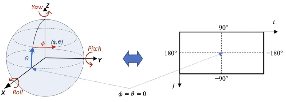
Equirectangular mapping is the most commonly used mapping from spherical video to a 2D texture signal. The mapping is bijective, i.e. it may be expressed in both directions and is illustrated in Figure A.2.

ERP has only one face and the face index f for ERP is always set to 0. The sphere coordinates (Φ, θ) for a sample location (i, j), in degrees, are given by the following equations:
Φ = (0.5 - i/pictureWidth)*360
θ = (0.5 - j/pictureHeight)*180
Finally, (X, Y, Z) can be calculated from the equations given above.
A.2.3.3 Cubemap Projection (CMP) p. 75
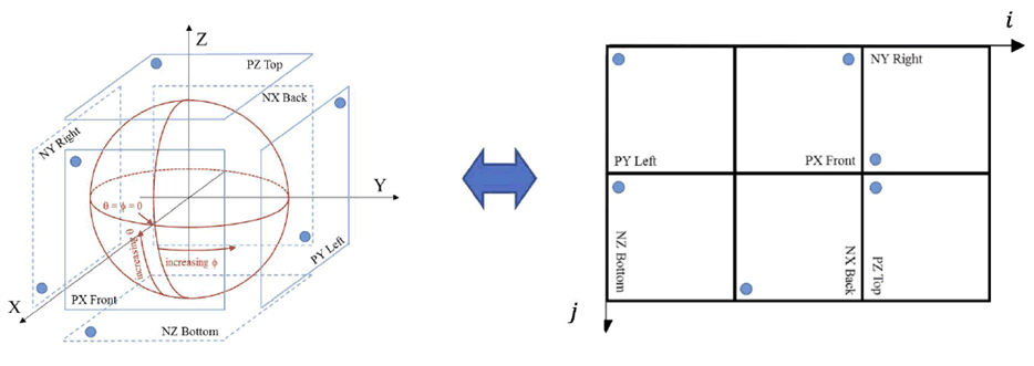
Figure A.3 shows the CMP projection with 6 square faces, labelled as PX, PY, PZ, NX, NY, NZ (with "P" standing for "positive" and "N" standing for "negative"). Table A.2-4 specifies the face index values corresponding to each of the six CMP faces.

Figure A.3: Relation of the cube face arrangement of the projected picture to the sphere coordinates
(⇒ copy of original 3GPP image)
(⇒ copy of original 3GPP image)
| Face index | Face label | Notes |
|---|---|---|
| 0 | PX | Front face with positive X axis value |
| 1 | NX | Back face with negative X axis value |
| 2 | PY | Left face with positive Y axis value |
| 3 | NY | Right face with negative Y axis value |
| 4 | PZ | Top face with positive Z axis value |
| 5 | NZ | Bottom face with negative Z axis value |
The 3D coordinates (X, Y, Z) are derived using following equations:
lw = pictureWidth / 3
lh = pictureHeight / 2
tmpHorVal = i − Floor( i ÷ lw ) * lw
tmpVerVal = j − Floor( j ÷ lh ) * lh
i' = −( 2 * tmpHorVal ÷ lw ) + 1
j' = −( 2 * tmpVerVal  ÷ lh ) + 1
w = Floor( i ÷ lw )
h = Floor( j ÷ lh )
if( w  = =  1  &&  h  = =  0 ) { // PX: positive x front face
 X = 1.0
 Y = i'
 Z = j'
} else if( w  = =  1  &&  h  = =  1 ) { // NX: negative x back face
 X = −1.0
 Y = −j'
 Z = −i'
} else if( w  = =  2  &&  h  = =  1 ) { // PZ: positive z top face
 X = −i'
 Y = −j'
 Z = 1.0
} else if( w  = =  0  &&  h  = =  1 ) { // NZ: negative z bottom face
 X = i'
 Y = −j'
 Z = −1.0
} else if( w  = =  0  &&  h  = =  0 ) { // PY: positive y left face
 X = −i'
 Y = 1.0
 Z = j'
} else { // ( w  = =  2  &&  h  = =  0 ), NY: negative y right face
 X = i'
 Y = −1.0
 Z = j'
}
A.2.3.4 Conversion between two projection formats p. 76
Denote (fd,id,jd) as a point (id,jd) on face fd in the destination projection format, and (fs,is,js) as a point (is,js) on face fs in the source projection format. Denote (X,Y,Z) as the corresponding coordinates in the 3D XYZ space. The conversion process starts from each sample position (fd,id,jd) on the destination projection plane, maps it to the corresponding (X,Y,Z) in 3D coordinate system, finds the corresponding sample position (fs,is,js) on the source projection plane, and sets the sample value at (fd,id,jd) based on the sample value at (fs,is,js).
Therefore, the projection format conversion process from ERP source format to CMP destination format is performed in the following three steps:
- Map the destination 2D sampling point (fd,id,jd) to 3D space coordinates (X,Y,Z) based on the CMP format.
- Map (X,Y,Z) from step 1 to 2D sampling point (f0,is,js) based to the ERP format.
- Calculate the sample value at (f0,is,js) by interpolating from neighboring samples at integer positions on face f0, and the interpolated sample value is placed at (fd,id,jd) in the destination projection format.