Content for TS 26.118 Word version: 18.0.0
4 Architectures and Interfaces for Virtual Reality
4.1 Definitions and Reference Systems
4.1.1 Overview
4.1.2 3GPP 3DOF Coordinate System
4.1.3 Video Signal Representation
4.1.4 Audio Signal Representation
...
...
4 Architectures and Interfaces for Virtual Reality p. 11
4.1 Definitions and Reference Systems p. 11
4.1.1 Overview p. 11
Virtual reality is a rendered version of a delivered visual and audio scene. The rendering is designed to mimic the visual and audio sensory stimuli of the real world as naturally as possible to an observer or user as they move within the limits defined by the application.
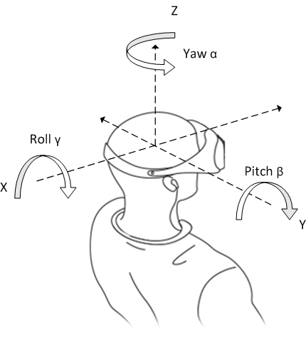
Virtual reality usually, but not necessarily, assumes a user to wear a head mounted display (HMD), to completely replace the user's field of view with a simulated visual component, and to wear headphones, to provide the user with the accompanying audio as shown in Figure 4.1-1.

Some form of head and motion tracking of the user in VR is usually also necessary to allow the simulated visual and audio components to be updated in order to ensure that, from the user's perspective, items and sound sources remain consistent with the user's movements. Sensors typically are able to track the user's pose in the reference system. Additional means to interact with the virtual reality simulation may be provided but are not strictly necessary.
VR users are expected to be able to look around from a single observation point in 3D space defined by either a producer or the position of one or multiple capturing devices. When VR media including video and audio is consumed with a head-mounted display or a smartphone, only the area of the spherical video that corresponds to the user's viewport is rendered, as if the user were in the spot where the video and audio were captured.
This ability to look around and listen from a centre point in 3D space is defined as 3 degrees of freedom (3DOF). According to the Figure 4.1-1:
- tilting side to side on the X-axis is referred to as Rolling, also expressed as γ
- tilting forward and backward on the Y-axis is referred to as Pitching, also expressed as β
- turning left and right on the Z-axis is referred to as Yawing, also expressed as α
4.1.2 3GPP 3DOF Coordinate System p. 12
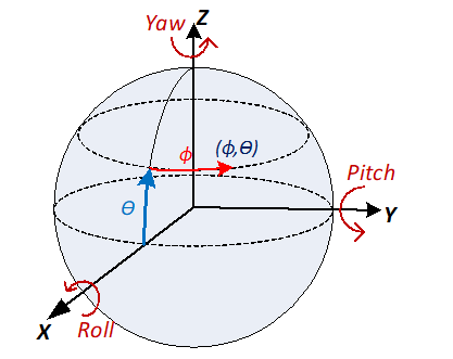
The coordinate system is specified for defining the sphere coordinates azimuth (ϕ) and elevation (θ) for identifying a location of a point on the unit sphere, as well as the rotation angles yaw (αα), pitch (ββ), and roll (γγ). The origin of the coordinate system is usually the same as the centre point of a device or rig used for audio or video acquisition as well as the position of the user's head in the 3D space in which the audio or video are rendered. Figure 4.1-2 specifies principal axes for the coordinate system. The X axis is equal to back-to-front axis, Y axis is equal to side-to-side (or lateral) axis, and Z axis is equal to vertical (or up) axis. These axis map to the reference system in Figure 4.1-1.

Signals defined in the present document are represented in a spherical coordinate space in angular coordinates (Φ,θ) for use in omnidirectional video and 3D audio. The viewing and listing perspective are from the origin sensing/looking/hearing outward toward the inside of the sphere. Even though a spherical coordinate is generally represented by using radius, elevation, and azimuth, it assumes that a unit sphere is used for capturing and rendering of VR media. Thus, a location of a point on the unit sphere is identified by using the sphere coordinates azimuth (ϕ) and elevation (θ). The spherical coordinates are defined so that Φ is the azimuth and θ is the elevation. As depicted in Figure 4.1-2, the coordinate axes are also used for defining the rotation angles yaw (αα), pitch (ββ), and roll (γγ). The angles increase clockwise when looking from the origin towards the positive end of an axis. The value ranges of azimuth, yaw, and roll are all −180.0, inclusive, to 180.0, exclusive, degrees. The value range of elevation and pitch are both −90.0 to 90.0, inclusive, degrees.
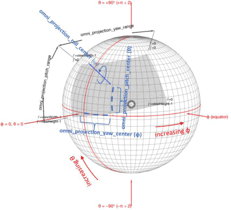
Depending on the applications or implementations, not all angles may be necessary or available in the signal. The 360 video may have a restricted coverage as shown in Figure 4.1-3. When the video signal does not cover the full sphere, the coverage information is described by using following parameters:
- centre azimuth: specifies the azimuth value of the centre point of sphere region covered by the signal.
- centre elevation: specifies the elevation value of the centre of sphere region.
- azimuth range: specifies the azimuth range through the centre point of the sphere region.
- elevation range: specifies the elevation range through the centre point of the sphere region.
- tilt angle: indicates the amount of tilt of a sphere region, measured as the amount of rotation of the sphere region along the axis originating from the origin passing through the centre point of the sphere region, where the angle value increases clockwise when looking from the origin towards the positive end of the axis.

Figure 4.1-3: Restricted coverage of the sphere region covered by the cropped output picture with omni_projection_{yaw | pitch | roll}_center the center of the coverage region
(⇒ copy of original 3GPP image)
(⇒ copy of original 3GPP image)
For video, such a centre point may exist for each eye, referred to as stereo signal, and the video consists of three colour components, typically expressed by the luminance (Y) and two chrominance components (U and V).
The coordinate systems for all media types are assumed to be aligned in 3GPP 3DOF coordinate system. Within this coordinate system, the pose is expressed by a triple of azimuth, elevation, and tilt angle characterizing the head position of a user consuming the audio-visual content. The pose is generally dynamic, and the information may be provided through sensors in a frequently sampled version.
The field of view (FoV) of a rendering device is static and defined in two dimensions, the horizontal and vertical FoV, each in units of degrees in the angular coordinates (Φ,θ). The pose together with the field of view of the device enables the system to generate the user viewport, i.e., the presented part of the content at a specific point in time.
4.1.3 Video Signal Representation p. 14
Commonly used video encoders cannot directly encode spherical videos, but only 2D textures. However, there is a significant benefit to reuse conventional 2D video encoders. Based on this, Figure 4.1-4 provides the basic video signal representation in the context of omnidirectional video in the context of the present document. By pre-processing, the spherical video is mapped to a 2D texture. The 2D texture is encoded with a regular 2D video encoder and the VR rendering metadata (i.e. the data describing the mapping from the spherical coordinate to the 2D texture) is encoded and provided along with the video bitstream, such that at the receiving end the inverse process can be applied to reconstruct the spherical video.

Mapping of a spherical picture to a 2D texture signal is illustrated in Figure 4.1-5. The most commonly used mapping from spherical to 2D is the equirectangular projection (ERP) mapping. The mapping is bijective, i.e. it may be expressed in both directions.

Following the definitions in clause 4.1.2, the mapping of the colour samples of 2D texture images onto a spherical coordinate space in angular coordinates (Φ,θ) for use in omnidirectional video applications for which the viewing perspective is from the origin looking outward toward the inside of the sphere. The spherical coordinates are defined so that Φ is the azimuth and θ is the elevation.
Assume a 2D texture with pictureWidth and pictureHeight, being the width and height, respectively, of a monoscopic projected luma picture, in luma samples and the center point of a sample location (i,j) along the horizontal and vertical axes, respectively, then for the equirectangular projection the sphere coordinates (ϕ,θ) for the luma sample location, in degrees, are given by the following equations:
ϕ = ( 0.5 − i ÷ pictureWidth ) * 360
θ = ( 0.5 − j ÷ pictureHeight ) * 180
Whereas ERP is commonly used for production formats, other mappings may be applied, especially for distribution. The present document also introduces cubemap projection (CMP) for distribution in clause 5. In addition to regular projection, other pre-processing may be applied to the spherical video when mapped into 2D textures. Examples include region-wise packing, stereo frame packing or rotation. The present document defines different pre- and post-processing schemes in the context of video rendering schemes.
4.1.4 Audio Signal Representation p. 15
Audio for VR can be produced using three different formats. These are broadly known as channels-, objects- and scene-based audio formats. Audio for VR can use any one of these formats or a hybrid of these (where all three formats are used to represent the spherical soundfield). The audio signal representation model is shown in Figure 4.1-6.
The present document expects that an audio encoding system is capable to produce suitable audio bitstreams that represent a well-defined audio signal in the reference system as defined in clause 4.1.1. The coding and carriage of the VR Audio Rendering Metadata is expected to be defined by the VR Audio Encoding system. The VR Audio Receiving system is expected to be able to use the VR Audio Bitstream to recover audio signals and VR Audio Rendering metadata. Both signals, audio signals and metadata, are well-defined by the media profile, such that different audio rendering systems may be used to render the audio based on the decoder audio signals, VR audio rendering metadata and the user position.
In the present document, all media profiles are defined such that for each media profile at least one Audio Rendering System is defined as a reference renderer and additional Audio Rendering systems may be defined. The audio rendering system is described based on well-defined output of the VR Audio decoding system.

For more details on audio rendering, refer to clause 4.5.