Content for TS 24.501 Word version: 19.1.1
1…
3…
4…
4.4…
4.4.3…
4.5…
4.5.3…
4.6…
4.7…
4.9…
4.15…
5…
5.2…
5.3…
5.3.2…
5.3.7…
5.3.19…
5.4…
5.4.1.3…
5.4.2…
5.4.4…
5.4.5…
5.4.6…
5.5…
5.5.1.2.4
5.5.1.2.5…
5.5.1.3…
5.5.1.3.4
5.5.1.3.5…
5.5.2…
5.6…
5.6.2…
6…
6.1.4…
6.2…
6.3…
6.3.2…
6.3.3…
6.4…
6.4.1.4…
6.4.2…
6.5…
7…
8…
8.2.9…
8.3…
9…
9.11.2…
9.11.2.10…
9.11.3…
9.11.3.4…
9.11.3.8…
9.11.3.14…
9.11.3.18C…
9.11.3.29…
9.11.3.33…
9.11.3.39…
9.11.3.45…
9.11.3.50…
9.11.3.53A…
9.11.3.68…
9.11.3.75…
9.11.4…
9.11.4.10…
9.11.4.13…
9.11.4.16…
9.11.4.30…
9.12
10…
A…
B…
C…
D…
D.6…
D.6.3…
D.6.8
D.7…
9.11.3.45 PLMN list
9.11.3.46 Rejected NSSAI
9.11.3.46A Release assistance indication
9.11.3.47 Request type
9.11.3.48 S1 UE network capability
9.11.3.48A S1 UE security capability
9.11.3.49 Service area list
...
...
9.11.3.45 PLMN list p. 946
9.11.3.46 Rejected NSSAI p. 946
The purpose of the Rejected NSSAI information element is to identify a collection of rejected S-NSSAIs.
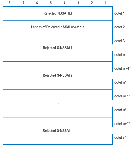
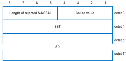
The Rejected NSSAI information element is coded as shown in Figure 9.11.3.46.1, Figure 9.11.3.46.2 and Table 9.11.3.46.1.
The Rejected NSSAI is a type 4 information element with a minimum length of 4 octets and a maximum length of 42 octets.
| Value part of the Rejected NSSAI information element (octet 3 to v) | |
| The value part of the Rejected NSSAI information element consists of one or more rejected S-NSSAIs. Each rejected S-NSSAI consists of one S-NSSAI and an associated cause value. The length of each rejected S-NSSAI can be determined by the 'length of rejected S-NSSAI' field in the first octet of the rejected S-NSSAI. The UE shall store the complete list received (NOTE 0). If more than 8 rejected S-NSSAIs are included in this information element, the UE shall store the first 8 rejected S-NSSAIs and ignore the remaining octets of the information element. | |
| Rejected S-NSSAI: | |
| Cause value (octet 3) | |
| Bits
4 3 2 1 | |
| 0 0 0 0 | S-NSSAI not available in the current PLMN or SNPN |
| 0 0 0 1 | S-NSSAI not available in the current registration area |
| 0 0 1 0 | S-NSSAI not available due to the failed or revoked network slice-specific |
| All other values are reserved. | |
| Slice/service type (SST) (octet 4) | |
| This field contains the 8 bit SST value. The coding of the SST value part is defined in TS 23.003. (NOTE 2) | |
| Slice differentiator (SD) (octet 5 to octet 7) | |
| This field contains the 24 bit SD value. The coding of the SD value part is defined in TS 23.003. (NOTE 3) | |
|
NOTE 0:
The number of rejected S-NSSAI(s) shall not exceed eight.
NOTE 1:
If octet 5 is included, then octet 6 and octet 7 shall be included.
NOTE 2:
If the Cause value is "S-NSSAI not available due to the failed or revoked network slice-specific authentication and authorization", this field shall contain the 8 bit SST value of an S-NSSAI in the S-NSSAI(s) of the HPLMN.
NOTE 3:
If the Cause value is "S-NSSAI not available due to the failed or revoked network slice-specific authentication and authorization", this field, if included, shall contain the 24 bit SD value of an S-NSSAI in the S-NSSAI(s) of the HPLMN.
|
|
9.11.3.46A Release assistance indication |R16| p. 948
9.11.3.47 Request type p. 948
The purpose of the Request type information element is to indicate the type of the 5GSM message.
The Request type information element is coded as shown in Figure 9.11.3.47.1 and Table 9.11.3.47.1.
The Request type is a type 1 information element.

| Request type value (octet 1, bit 1 to bit 4) | |
| Bits
3 2 1 | |
| 0 0 1 | initial request |
| 0 1 0 | existing PDU session |
| 0 1 1 | initial emergency request |
| 1 0 0 | existing emergency PDU session |
| 1 0 1 | modification request |
| 1 1 0 | MA PDU request (NOTE) |
| 1 1 1 | reserved |
| All other values are unused and shall be interpreted as "initial request", if received by the network. | |
|
NOTE:
This value shall be interpreted as "initial request", if received by a network not supporting MA PDU sessions.
|
|
9.11.3.48 S1 UE network capability p. 949
9.11.3.48A S1 UE security capability p. 949
9.11.3.49 Service area list p. 949
The purpose of the Service area list information element is to transfer a list of allowed tracking areas for an allowed area or a list of non-allowed tracking areas for a non-allowed area from the network to the UE.
The coding of the information element allows combining different types of lists. The lists of type "00" and "01" allow a more compact encoding, when the different TAIs are sharing the PLMN identity. The lists of type "11" indicate all TAIs of the PLMNs in the registration area are allowed area.
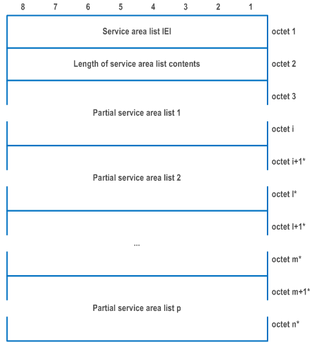
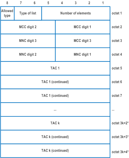
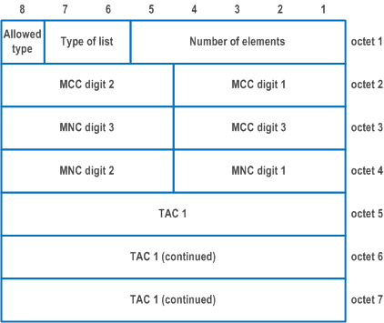
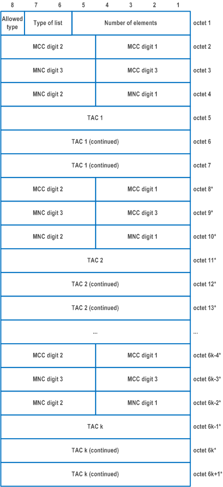
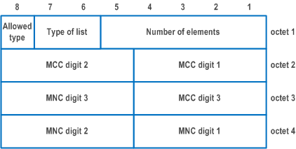
The Service area list information element is coded as shown in Figure 9.11.3.49.1, Figure 9.11.3.49.2, Figure 9.11.3.49.3, Figure 9.11.3.49.4, Figure 9.11.3.49.5 and Table 9.11.3.49.1.
The Service area list is a type 4 information element with a minimum length of 6 octets and a maximum length of 114 octets. The list can contain a maximum of 16 different tracking area identities.
| Value part of the Service area list information element (octets 3 to n) | |
| The value part of the Service area list information element consists of one or several partial service area lists. The length of each partial service area list can be determined from the 'type of list' field and the 'number of elements' field in the first octet of the partial service area list. The "Allowed type" fields in all the partial service area lists shall have the same value. For allowed type "0", TAIs contained in all partial service area lists are in the allowed area. For allowed type "1", TAIs contained in all partial service area lists are in the non-allowed area. The UE shall store the complete list received. If more than 16 TAIs are included in this information element, the UE shall store the first 16 TAIs and ignore the remaining octets of the information element. | |
| Partial service area list: | |
| Allowed type (octet 1) | |
| Bit
8 | |
| 0 | TAIs in the list are in the allowed area |
| 1 | TAIs in the list are in the non-allowed area |
| Type of list (octet 1) | |
| Bits
7 6 | |
| 0 0 | list of TACs belonging to one PLMN, with non-consecutive TAC values |
| 0 1 | list of TACs belonging to one PLMN, with consecutive TAC values |
| 1 0 | list of TAIs belonging to different PLMNs (see NOTE) |
| 1 1 | All TAIs belonging to the PLMNs in the registration area are in the allowed area |
| Number of elements (octet 1) | |
| Bits
5 4 3 2 1 | |
| 0 0 0 0 0 | 1 element |
| 0 0 0 0 1 | 2 elements |
| 0 0 0 1 0 | 3 elements |
| to 0 | |
| 0 1 1 0 1 | 14 elements |
| 0 1 1 1 0 | 15 elements |
| 0 1 1 1 1 | 16 elements |
| All other values are unused and shall be interpreted as 16, if received by the UE. | |
| For type of list = "00" and number of elements = k: | |
| octets 2 to 4 contain the MCC+MNC, and
for j = 1, …, k: octets 3j+2 to 3j+4 contain the TAC of the j-th TAI belonging to the partial list, | |
| For type of list = "01" and number of elements = k: | |
| octets 2 to 4 contain the MCC+MNC, and
octets 5 to 7 contain the TAC of the first TAI belonging to the partial list. The TAC values of the other k-1 TAIs are TAC+1, TAC+2, …, TAC+k-1. | |
| For type of list = "10" and number of elements = k: | |
| for j = 1, …, k.
octets 6j-4 to 6j-2 contain the MCC+MNC, and octets 6j-1 to 6j+1 contain the TAC of the j-th TAI belonging to the partial list. | |
| For type of list = "11": | |
|
Allowed type shall be coded as "0" and number of elements shall be ignored, and octets 2 to 4 containing the MCC+MNC can be ignored.
If allowed type is coded as "1", it shall be interpreted as "0". | |
| MCC, Mobile country code | |
| The MCC field is coded as in ITU-T Recommendation E.212 [42], Annex A. | |
| MNC, Mobile network code | |
| The coding of this field is the responsibility of each administration but BCD coding shall be used. The MNC shall consist of 2 or 3 digits. If a network operator decides to use only two digits in the MNC, MNC digit 3 shall be coded as "1111". | |
| TAC, Tracking area code | |
| In the TAC field bit 8 of the first octet is the most significant bit and bit 1 of the third octet the least significant bit. The coding of the tracking area code is the responsibility of each administration. Coding using full hexadecimal representation may be used. The tracking area code consists of 3 octets. | |
|
NOTE:
If the "list of TAIs belonging to different PLMNs" is used, the PLMNs included in the list need to be present in the list of equivalent PLMNs. This type is not applicable in an SNPN.
|
|