Content for TS 24.011 Word version: 18.0.0
2 Overview of Short Message Service (SMS) support
2.1 Protocols and protocol architecture
2.2 Use of channels (A/Gb mode only)
2.3 Layer 2 SAPI 3 handling for circuit switched in A/Gb mode
2.4 Layer 2 (LLC) GPRS support (A/Gb mode only)
2.5 GSMS entity in Iu mode
2.5A ESMS entity in S1 mode
2.5B 5GSMS entity in N1 mode
2.6 MS support for SMS over GPRS
2.7 MS support for device triggering short message
...
...
2 Overview of Short Message Service (SMS) support p. 9
The purpose of the Short Message Service is to provide the means to transfer messages between a GSM PLMN Mobile Station (MS) and a Short Message Entity via a Service Centre, as described in TS 23.040. The terms "MO" - Mobile Originating - and "MT" - Mobile Terminating - are used to indicate the direction in which the short message is sent.
The present document describes the procedures necessary to support the Short Message Service between the MS and the MSC or SGSN or MME or SMSF and vice versa, as described in TS 23.040.
The procedures are based on services provided by the Mobility Management sublayer as described in TS 24.007/TS 24.008 for CS in A/Gb mode and CS/PS services in Iu mode, 3GPP 24.301 [10] for CS/PS services in S1 mode, TS 24.501 for N1 mode and the Logical Link Control layer described in TS 44.064 for GPRS services. For CS/PS service in S1 mode, depending on network configuration and UE subscription data, network may choose to use either packet-switched service or circuit-switched service to provide SMS service. If circuit-switched service is used instead of packet-switched service, then the messages are tunneled through the MME. In this case the network also uses procedures described in 3GPP 29.118 [12].
2.1 Protocols and protocol architecture p. 10
In Iu mode only, integrity protected signalling (see TS 24.008, subclause 'Integrity Protection of Signalling Messages' and in general, see TS 33.102) is mandatory. In Iu mode only, all protocols shall use integrity protected signalling. Integrity protection of all SMS signalling messages is the responsibility of lower layers. It is the network which activates integrity protection. This is done using the security mode control procedure (TS 25.331).
The hierarchical model in Figure 2.1a shows the layer structure of the MSC and the MS in A/Gb mode. The hierarchical model in Figure 2.1c shows the layer structure of the SGSN and the MS in Iu mode. The hierarchical model in Figure 2.1d shows the layer structure of the MSC and the MS in S1 mode. The hierarchical model in Figure 2.1e shows the layer structure of the MME and the MS in S1 mode.
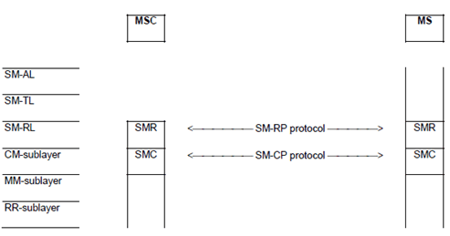
The hierarchical model in Figure 2.1b shows the layer structure of the SGSN and the MS in A/Gb mode.
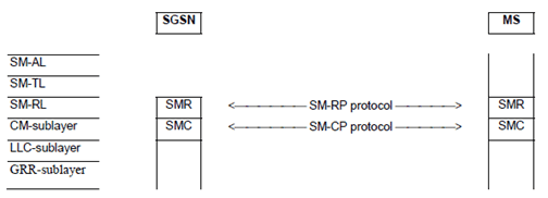

Figure 2.1c: Protocol hierarchy for packet-switched service in Iu mode
(⇒ copy of original 3GPP image)
(⇒ copy of original 3GPP image)
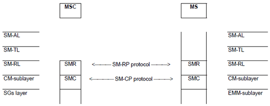
Figure 2.1d: Protocol hierarchy for circuit-switched service in S1 mode
(⇒ copy of original 3GPP image)
(⇒ copy of original 3GPP image)

Figure 2.1e: Protocol hierarchy for packet-switched service in S1 mode
(⇒ copy of original 3GPP image)
(⇒ copy of original 3GPP image)
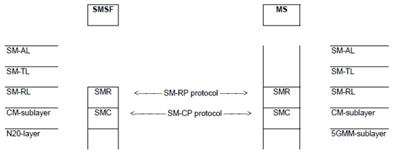
The CM-sublayer, in terms of the Short Message Service Support, provides services to the Short Message Relay Layer.
On the MS-side the Short Message Relay Layer provides services to the Short Message Transfer Layer. The Short Message Relay Layer is the upper layer on the network side (MSC or SGSN or MME), and the SM-user information elements are mapped to TCAP/MAP.
The peer protocol between two SMC entities is denoted SM-CP, and between two SMR entities, SM-RP.
Abbreviations:
SM-AL
Short Message Application Layer
SM-TL
Short Message Transfer Layer
SM-RL
Short Message Relay Layer
SM-RP
Short Message Relay Protocol
SMR
Short Message Relay (entity)
CM-sub
Connection Management sublayer
SM-CP
Short Message Control Protocol
SMC
Short Message Control (entity)
MM-sub
Mobility Management sublayer
GMM-sub
GPRS Mobility Management sublayer
RR-sub
Radio Resource Management sublayer
LLC-sub
Logical Link Control sublayer
GRR-sub
GPRS Radio Resource sublayer in GSM
EMM-sub
EPS Mobility Management sublayer
5GMM-sub
5G Mobility Management sublayer
2.2 Use of channels (A/Gb mode only) p. 12
Table 2.1 summarizes the use of channels for the short message service for circuit switched in A/Gb mode. Arrows indicate changes of channel.
| Channel dependency | Channel used |
|---|---|
| TCH not allocated | SDCCH |
| TCH not allocated → TCH allocated | SDCCH → SACCH |
| TCH allocated | SACCH |
| TCH allocated → TCH not allocated | SACCH → SACCH opt. SDCCH³ |
The short message service for GPRS shall be supported by a PDTCH.
2.3 Layer 2 SAPI 3 handling for circuit switched in A/Gb mode p. 13
General rule:
- the Radio Resource Management (RR reference TS 44.018) in the Mobile Station and on the network side (i.e. in the BSC) shall establish the acknowledged mode of operation on SAPI 3 whenever needed, i.e. when a message requiring SAPI 3 transfer shall be transmitted;
- RR shall control the layer 2 also for SAPI 3, and keep knowledge of the mode;
- the network side may initiate release of the acknowledged mode for SAPI 3 either explicitly (by the use of DISC- and UA-frames, see TS 44.006) or indirectly by channel release (see TS 44.018).
- the Mobile Station side will initiate establishment of SAPI 3 acknowledged mode in the case of mobile originating short message transfer;
- the network side will initiate establishment of SAPI 3 acknowledged mode in the case of mobile terminating short message transfer;
- the network side may choose to keep the channel and the acknowledged mode of operation to facilitate transfer of several short messages for or from the same Mobile Station. The queuing and scheduling function for this should reside in the MSC.
2.4 Layer 2 (LLC) GPRS support (A/Gb mode only) p. 13
It shall be possible for a GPRS-attached MS of any class (A, B, C) to send and receive short messages over GPRS radio channels.
GPRS shall use the unacknowledged mode of LLC frame transfer as described in TS 44.064, and shall use SAPI 7 to identify the SMS Logical Link Entity within the LLC layer.
A description of the different GPRS MS classes can be found in TS 23.060, and a brief overview is given below:
- class A/B MSs may be able to send and receive short messages using either the MM sublayer (using SACCH or SDCCH) or the LLC layer (using PDTCH);
- class C MSs may be able to send and receive short messages using only the LLC layer (using the PDTCH). The capability for GPRS-attached class-C MSs to receive and transmit SMS messages is optional.
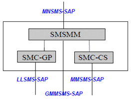
2.5 GSMS entity in Iu mode p. 14
It shall be possible for a PS-attached MS of any mode of operation to send and receive short messages in Iu mode.
A description of the different mode of operation UMTS MS can be found in TS 23.060, and a brief overview is given below:
- CS/PS mode of operation MSs may be able to send and receive short messages using either the MM sublayer or the GMM sublayer;
- PS mode of operation MSs may be able to send and receive short messages using only GMM sublayer.
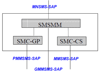
The Radio Resource Management shall use the 'low priority' class for the downlink transfer of SMS signalling messages. This means the core network shall set the SAPI value to 3 in RANAP Direct Transfer messages (see TS 25.413) when sending SMS signalling messages over the Iu interface.
2.5A ESMS entity in S1 mode |R8| p. 15
It shall be possible for an MS that is attached to CS and PS or attached for PS to send and receive short messages in S1 mode.
A description of the different modes of operation for E-UTRAN MS can be found in TS 24.301:
- if the MS is attached to CS and PS, an overview of SMS services in S1 mode can be found in TS 23.272. In S1 mode, the network may choose to use either circuit-switched service or packet-switched service to provide SMS services (see subclause 2.1). If circuit-switched service is used by the network, then messages are tunnelled through the PS domain between the MS and the MSC, and otherwise have no impact on PS domain operation. If packet-switched service is used by the network, then messages are transferred between the MS and the MME.
- if the MS is attached for PS (see TS 24.301), the MS may be able to send and receive short messages using only EMM sublayer. In this case, short messages are transferred between the MS and the MME.

2.5B 5GSMS entity in N1 mode |R15| p. 15
It shall be possible for an MS in N1 mode that is attached to the 5GCN to send and receive short messages.
The 5GSMS entity for an MS in N1 mode is shown in Figure 2.5B.

2.6 MS support for SMS over GPRS |R5| p. 16
If the MS is attached to GPRS and the circuit-switched domain, and an SMS transfer via GPRS fails either due to a reception of an RP-ERROR message with cause #69 or due to the complete lack of network response, then the MS shall take the following actions:
- The MS shall use the circuit-switched domain instead of GPRS for SMS transfer for an implementation dependent time. When a different PLMN is selected, if the MS preferred method is the sending of SMS over GPRS, the MS shall revert to trying an SMS transfer via GPRS.
- If the SMS transfer failed in both GPRS and the circuit-switched domain, the user shall be informed.
2.7 MS support for device triggering short message |R15| p. 16
If the UE is attached for EPS services, supports non-IP PDN type as specified in TS 24.301 and supports the device triggering short message as specified in TS 23.040, then upon receiving a device triggering short message with the Application port addressing information element set to "trigger to establish a PDN connection of non-IP PDN type using the default APN" as specified in TS 23.040, the UE shall send to the ESM entity as specified in TS 24.007 an indication requesting establishment of a PDN connection for non-IP PDN type using the default APN.