Content for TS 23.586 Word version: 18.6.0
6.7 Procedures for Ranging/SL Positioning service exposure
6.7.1 Procedures for service exposure to SL Positioning Client UE
6.7.2 Procedures for Service Exposure to the AF
6.8 Procedures of Ranging/Sidelink Positioning control
6.7 Procedures for Ranging/SL Positioning service exposure p. 43
6.7.1 Procedures for service exposure to SL Positioning Client UE p. 43
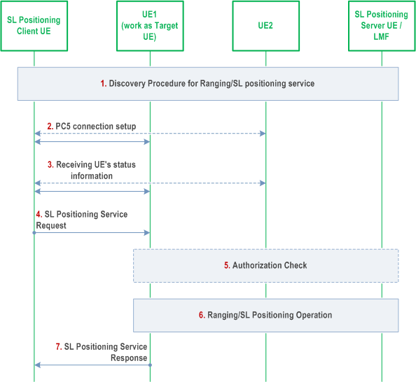
6.7.1.1 Procedures for Ranging/SL Positioning service exposure through PC5 p. 43

Step 1.
When a Ranging/SL Positioning service is triggered, SL Positioning Client UE may perform discovery procedure for the Ranging/SL Positioning service defined in clause 6.4 with following updates:
Step 2.
- When SL positioning service is triggered, the client UE tries to discover the target UE and/or one or more SL Reference UE(s)/Located UE(s). When Model B discovery used, in the Solicitation message, target UE's user info is included and role of target UE and role of SL Reference UE/Located UE are indicated in the RSPP metadata.
- When Ranging service is triggered, the client UE tries to discover UE1 and/or UE2. When Model B discovery used, in the Solicitation message, UE1's user info and UE2's user info are included and role of target UE is indicated in the RSPP metadata.
If discovery procedure succeeds, the SL Positioning Client UE establishes a PC5 connection with the discovered UE.
The SL Positioning Client UE may receive a supplementary RSPP signalling message including list of SL Reference UE(s)/Located UE(s) from target UE over the PC5 connection.
Step 3.
The SL Positioning Client UE may select UE(s) to perform SL Positioning operation and select a UE (here UE1) to receive SL Positioning Service Request. The SL Positioning Client UE sends a SL Positioning Service Request using supplementary RSPP signalling message.
For absolute location, the SL Positioning Client UE sends a SL Positioning Service Request which includes info of SL Positioning Client UE, info of Target UE, and required positioning QoS. The Service Request may include info of list of candidate Located UE(s).
For relative location, the SL Positioning Client UE sends a SL Positioning Service Request which includes info of SL Positioning Client UE, info of Target UE, info of SL Reference UE(s), and required positioning QoS.
For ranging, the SL Positioning Client UE sends a SL Positioning Service Request which includes info of SL Positioning Client UE, info of UE1, info of UE2, and required positioning QoS.
For ranging, if UE1 and UE2 are not in proximity, the SL Positioning Service Request is responded with reject by the receiving UE (either UE1 or UE2) and remaining steps are not performed.
Step 4.
The UE which received SL Positioning Service Request (here UE1) selects LMF or SL Positioning Server UE based on its status whether UE has NAS connection.
Step 5.
- If SL Positioning Server UE is selected (the Server UE can be the Target UE itself or a UE different from the Target UE), Ranging/SL Positioning operation is performed as described in clause 6.8.
- If LMF is selected, UE1 first checks with UE2/.../UEn about whether exposure to SL Positioning Client UE is allowed based on the procedure defined in clause 6.3.6.3 of TS 33.533. If the privacy check is successful, the Ranging/SL Positioning operation is then performed as described in clause 6.20.1 of TS 23.273.
The Ranging/SL Positioning result is provided to the SL Positioning client UE by UE1.
6.7.1.2 Void
6.7.2 Procedures for Service Exposure to the AF p. 44
SL-MT-LR procedure defined in clause 6.20.3 of TS 23.273 is performed for Service Exposure to the 5GC NF, AF or the LCS Client.
6.8 Procedures of Ranging/Sidelink Positioning control p. 44
Either UE-only Operation or Network-based Operation is applied in the Ranging/Sidelink Positioning control procedures.
UE-only Operation as specified in this clause is applied for the following cases:
- Neither Target UE nor SL Reference UE is served by NG-RAN.
- Network-based Operation is not supported by the 5GC network as described in clause 5.2.3.
- Response to SL-MO-LR request allows the UE only operation for a period of time by the network due to congestion.

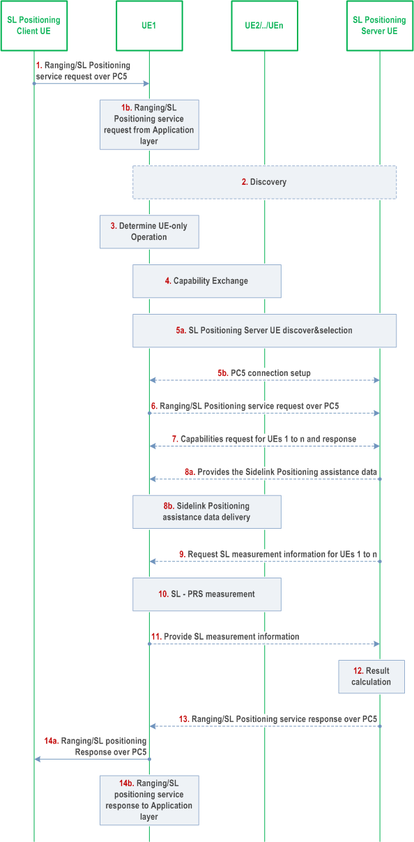
Step 1.
UE1 (i.e. Target UE) may receive a Ranging/SL Positioning Service request from:
Step 1a.
SL Positioning Client UE over PC5 during procedures for Ranging/SL Positioning service exposure through PC5 as defined in clause 6.7.1.1.
For absolute location, the service request includes the SL Positioning Client UE's user info and Target UE's user info, and required positioning QoS and may also include the user info for a list of candidate Located UE(s).
For relative location or ranging information, the service request includes the SL Positioning Client UE's user info, Target UE's user info, SL Reference UE's user info (UE2/.../UEn), and Ranging/SL Positioning QoS information.
Step 1b.
RSPP application layer.
The service request includes type of the result (i.e. absolute location, relative location or ranging information) and the required QoS.
Step 2.
If exposure to SL Positioning Client UE is allowed by UE1, it discovers UE2/.../UEn (i.e. SL Reference UEs/Located UEs and optionally whether they support SL Positioning Server UE role) as defined in clause 6.4, if needed.
Step 3.
If none of UE1/.../UEn are served by NG-RAN or the serving network does not support Ranging/SL Positioning, UE-only Operation is applied.
Step 4.
UE1 and UE2/.../UEn perform capability exchange using SLPP messages. Step 4 may be performed during step 7 with coordination of SL Positioning Server UE.
Before the step4, UE1 establishes the secure PC5 link with UE2/.../UEn.
In addition, if UE1 acts as SL Positioning Server, UE1 may also request for the absolute location of UE2/.../UEn from UE2/.../UEn using the supplementary RSPP signalling message, and if the absolute location is available and allowed to be shared (i.e. after privacy verification according to clause 6.3.7 of TS 33.533), the absolute location of UE2/.../UEn is transferred by UE2/.../UEn to UE1 by the supplementary RSPP signalling message; and
UE1 selects the Located UEs (e.g. UEx/.../UEy) from UE2/.../UEn for the subsequent SL positioning/ranging operation (e.g., based on information received during discovery, Ranging/SL Positioning capability of UE1/UE2/.../UEn, the absolute location of UE2/.../UEn).
Step 5.
If UE1 does not support SL Positioning Server functionalities or UE1 opts to select a SL Positioning Server UE different from UE1, a SL Positioning Server UE (either co-located with a SL Reference UE/Located UE, or operated by a separate UE) is discovered (if not yet discovered in step 2) and selected. If a SL Positioning Server UE is co-located with a SL Reference UE/Located UE or operated by a separate UE, UE1 discovers and selects the SL Positioning Server UE as described in clauses 5.2.3 and 6.4. UE1 establishes the secure PC5 link with the selected SL Positioning Server UE.
If the Located UE is served by NG-RAN, it may use 5GC-MO-LR procedure to retrieve its absolute location.
Step 6.
If a SL Positioning server UE is selected, UE 1 sends a Ranging/SL positioning request using supplementary RSPP signalling message to the selected SL Positioning Server UE. This request indicates the other UEs 2 to n using the Application layer ID and indicates the Ranging/SL positioning result types needed (e.g. absolute locations, relative locations or distances and directions between pairs of UEs). The required QoS for Ranging/SL positioning is also indicated.
Step 7.
The SL Positioning Server UE sends requests to UE1 for capability of UE1 using the SLPP message and for the capabilities of UE2/.../UEn using the supplementary RSPP signalling (e.g. including SLPP containers that may contain Sidelink Positioning capability request for UE2/.../UEn) message with the corresponding Application Layer ID of UE2/.../UEn. UE1 responds to the SL Positioning Server UE with its own capability using SLPP message and the capabilities of UE2 to n using the supplementary RSPP signalling message (e.g. including SLPP containers that may contain Sidelink Positioning capability of UE2/.../UEn) with the corresponding Application Layer ID of UE2/.../UEn. If step 4 did not occur, UE1 retrieves capabilities from UE2/.../UEn using SLPP messages during this step.
The SL Positioning Server UE may downselect the UEs (e.g. UEx/.../UEy) from UE2/.../UEn for the subsequent SL positioning/ranging operation (e.g., based on UE capability).
Step 8.
The SL Positioning Server UE provides the Sidelink Positioning assistance data to UE1.
Step 8a.
For the Sidelink Positioning assistance data used by UE1, it is transmitted by SLPP message.
Step 8b.
For the Sidelink Positioning assistance data used by UEx/.../UEy, it is transmitted using the supplementary RSPP signalling messages (e.g. including SLPP containers that may contain Sidelink Positioning assistance data for UEx/.../UEy) with the corresponding Application Layer ID of UEx/.../UEy and then UE1 sends the assistance data to each UE (UEx/.../UEy) by SLPP messages.
Step 9.
The SL Positioning Server UE sends requests to UE1 for SL measurement information of UE 1 and UEx/.../UEy, if the SL Positioning Server UE performs the result calculation. For the SL measurement information of UE1, the request uses the SLPP message. For the SL measurement information of UEx/.../UEy, the request uses the supplementary RSPP signalling message (e.g. including SLPP container that may contain Sidelink Positioning location measurements request for UEx/.../UEy) with the corresponding Application Layer ID of UEx/.../UEy. In addition, the SL Positioning Server UE may also request for the absolute location of UEx/.../UEy via UE1 using the supplementary RSPP signalling message with the corresponding Application Layer ID of UEx/.../UEy. If the absolute location of UEx/.../UEy is available, then the absolute location of UEx/.../UEy is returned using a supplementary RSPP signalling message.
Step 10.
If a SL Positioning Server UE different from UE1 is selected in step 5, SL-PRS measurement is performed between UE1 and UEx/.../UEy and possibly also amongst UEx/.../UEy. The UE1 requests for the SL measurement information from UEx/.../UEy by the SLPP messages and/or the absolute locations of UEx/.../UEy from UEx/.../UEy by supplementary RSPP signalling messages if requested in step9 by SL Positioning Server UE. The SL-PRS measurement data is transferred to UE1 using SLPP messages.
Step 11.
SL-PRS measurement data of UE1 is transferred by SLPP message to the SL Positioning Server UE and SL-PRS measurement data of UEx/.../UEy is transferred by UE1 using the supplementary RSPP signalling message (e.g. including SLPP container that may contain SL-PRS measurement data of UEx/.../UEy) with the corresponding Application Layer ID of UEx/.../UEy to the SL Positioning Server UE if requested in step 9 in order to perform result calculation. The absolute location of UEx/.../UEy as received in step 9 is transferred by UE1 to the SL Positioning Server UE by the supplementary RSPP signalling message with the corresponding Application Layer ID of UEx/.../UEy if requested in step 9.
Step 12.
Based on the result types requested in step 6, absolute location, relative location or ranging information is calculated at the SL Positioning Server UE.
Step 13.
The SL Positioning Server UE selected in step 5 sends a Ranging/SL positioning response using supplementary RSPP signalling message to UE1 including the result that is required in step 6.
Step 14.
Ranging/SL Positioning result is transferred to:
Step 14a.
SL Positioning Client UE over PC5 during procedures for Ranging/SL Positioning service exposure through PC5 as defined in clause 6.7.1.1;
Step 14b.
Application layer.