Content for TS 23.289 Word version: 19.3.0
0…
4…
4.7…
4.7.4…
4.8…
5…
5.4…
6…
6.3…
6.3.2…
7…
7.2.4…
7.3…
7.3.3…
7.3.3.2…
7.3.3.4…
7.3.3.5…
7.3.3.7…
7.3.3.8…
7.3.3.9…
7.3.3.10…
7.3.3.11…
7.3.3.12…
7.3.3.13…
7.4…
7.5…
7.6…
A…
4.7.4 Service layer-based interworking between eMBMS and MBS
4.7.5 Application layer based interworking between eMBMS and MBS
4.7.6 General architecture showcasing use of MBS by UE for MC services
...
...
4.7.4 Service layer-based interworking between eMBMS and MBS p. 20
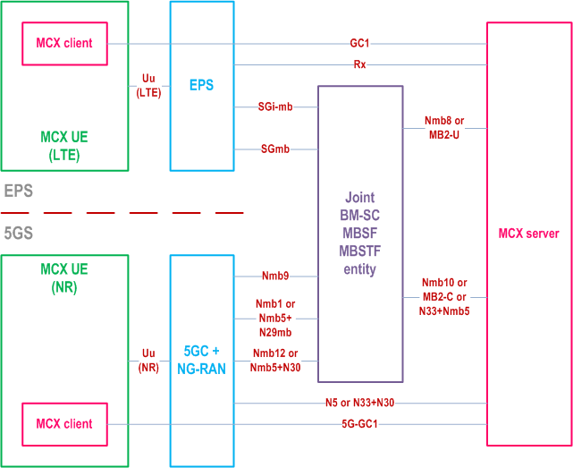
Figure 4.7.4-1 presents a high-level architectural view of mission critical services interworking between eMBMS and MBS at the service layer. The shown architecture is consistent with subclauses 5.2, 6.8 of TS 23.247, and configurations 2 and 3 in Annex A.
The interworking between eMBMS and MBS for mission critical operation is enabled by the Joint BM-SC, MBSF and MBSTF functional entity. MC services can use control plane capabilities by accessing the Joint entity directly via MB2-C or Nmb10 or indirectly (using NEF) via N33+Nmb5. User plane traffic delivery is supported via MB2-U or Nmb8. If the MC service server and the 5GS are in different trust domains with respect to MBS, N33 needs to be used to gain access to the MBS PCC capabilities.

4.7.5 Application layer based interworking between eMBMS and MBS p. 21
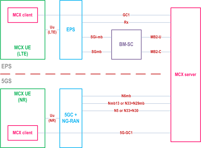
Figure 4.7.5-1 presents a high-level architectural view of mission critical services interworking between eMBMS and MBS at the application layer. The shown architecture does not use the MBSF/MBSTF entities defined in TS 23.247 and is inclusive of configuration 1 in Annex A of TS 23.247.
MC services initiate access to control plane capabilities via MB2-C (for eMBMS) and via Nmb13 or N33 (for MBS). User plane capabilities can be accessed via MB2-U (for eMBMS) and via N6mb (for MBS). MC service servers can initiate access to PCC capabilities via the Rx interface (for the PCRF in the EPS) and via the N5 or N33 interfaces (for the PCF in the 5GS). If the MC service server and the 5GS are in different trust domains with respect to MBS, N33 needs to be used to gain access to the MBS control plane capabilities and the PCC capabilities.

4.7.6 General architecture showcasing use of MBS by UE for MC services p. 22
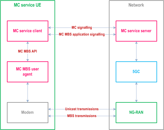
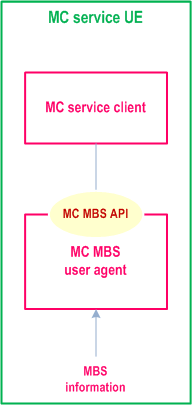
Figure 4.7.6-1 presents a high-level system architecture that shows how the MC service UEs support the delivery of mission critical services through MBS. Figure 4.7.6-2 shows the functional model used by the UE, highlighting the conceptual MC MBS API used for information transfer within the UE. The shown system architecture and functional model are analogous to the models described in TS 23.479 and consistent with TS 23.501 and TS 23.247.

The conceptual MC MBS API resides between the MC service client and the conceptual MC MBS user agent.

The MC service client uses information received from the MC service server through MC signalling (e.g., announcements) and through application-level signalling (e.g., mappings of MBS sessions and MBS subchannels to specific MC service groups) to communicate with the conceptual MC MBS user agent via the conceptual MC MBS API, in order to establish and update the proper communication context between the entities. Multiple MC service clients can be supported by the MC MBS user agent. The conceptual MC MBS user agent presents data and information received from the UE's lower layers to each MC service client according to the most recently established communication context. The functionalities of the MC service client and of the MC MBS user agent are described in clauses 4.3.2 and 4.3.3 of TS 23.479. The information flows and procedures described in TS 23.479 apply, with the following clarifications:
- References to "MBMS" (meaning 4G "eMBMS") are understood to be references to 5G "MBS";
- Unless used as in "multicast IP address", the stand-alone term "multicast" is understood as "broadcast or multicast";
- References to "SAI" are understood to be references to "MBS service areas", e.g., cell id, tracking area id, MBS frequency selection area id, as specified in TS 23.247;
- References to (e)MBMS 4G "bearer" are understood to be references to 5G "MBS session" and references to 4G "TMGI" are understood to be references to 5G "MBS session ID"; and
- "Cell information", used in cell information responses and cell update notifications in 5G, contains not only the id of the cell the MC UE is being served by, but also the RRC state of the MC service UE in the cell (i.e., active, inactive, idle). 5G cell updates notify not only changes of the serving cell, but also changes of RRC state for the MC UE, within the same cell.