Content for TS 23.272 Word version: 19.1.0
1…
4…
5…
5.4…
6…
6.3
6.4…
7…
7.3
7.4…
7.5a…
8…
8.2.4a…
8.3…
8.4…
B…
B.2…
B.2.2…
B.2.3a…
B.2.3a.4…
B.2.4…
B.3…
C…
C.8…
B.2.3a.4 Mobile Terminating Call without PS handover, or with concurrent non-optimised PS handover or optimised idle-mode PS handover
B.2.3a.5 Mobile Terminating Call with concurrent optimised PS handover
B.2.3a.6 Interaction between enhanced CS Fallback to 1xRTT and optimised PS handover
B.2.3b Mobile Originated or Mobile terminated call rejected by the MME
...
...
B.2.3a.4 Mobile Terminating Call without PS handover, or with concurrent non-optimised PS handover or optimised idle-mode PS handover p. 85
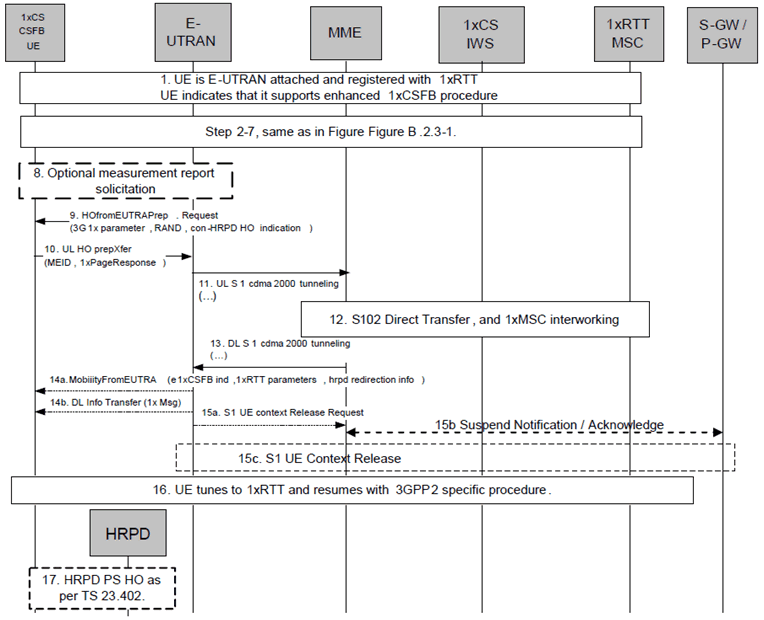
The following Figure describes the mobile terminating call procedures for the enhanced CS Fallback to 1xRTT with concurrent non-optimised PS handover or optimised idle-mode PS handover, or without PS handover, in the normal case. Clause B.2.3b describes the procedure when the procedure is rejected by the MME.

Figure B.2.3a.4-1: Enhanced CS fallback to 1xRTT MT call without PS handover, or with concurrent non-optimised PS handover or optimised idle-mode PS handover
(⇒ copy of original 3GPP image)
(⇒ copy of original 3GPP image)
Step 1.
UE is E-UTRAN attached and pre-registered with 1xRTT CS as defined in clause B.2.1.1 with enhanced CS fallback to 1xRTT capability indication to E-UTRAN. The UE may also indicate that it supports concurrent 1xRTT and HRPD capability The UE may also be pre-register with HRPD access using procedures defined in clause 9.3.1 of TS 23.402. The UE may also indicate support of enhanced CS fallback to 1xRTT for dual receiver/transmitter configuration to E-UTRAN.
Step 2-7.
Same as step 2-7 in Figure B.2.3-1.
If priority indication in included in the S1AP UE Context Setup or modification message from the MME to the E-UTRAN, the E-UTRAN shall not initiate enhanced 1xCSFB with concurrent optimized PS handover to HRPD access.
Step 8-17.
Same as steps 5 - 12 of Figure B.2.3a.2-1, with the modifications that the 1x message in step 7 of Figure B.2.3a.2-1 provided by the UE to the E-UTRAN is a 1xPage Response message and 1x messages in step 9a of Figure B.2.3a.2-1 (step 14a of Figure B.2.3a.4-1) provided by the E-UTRAN to UE may also contain Alert With Information message to provide caller line Identification and alerting trigger with 1x channel assignment message.
B.2.3a.5 Mobile Terminating Call with concurrent optimised PS handover p. 86
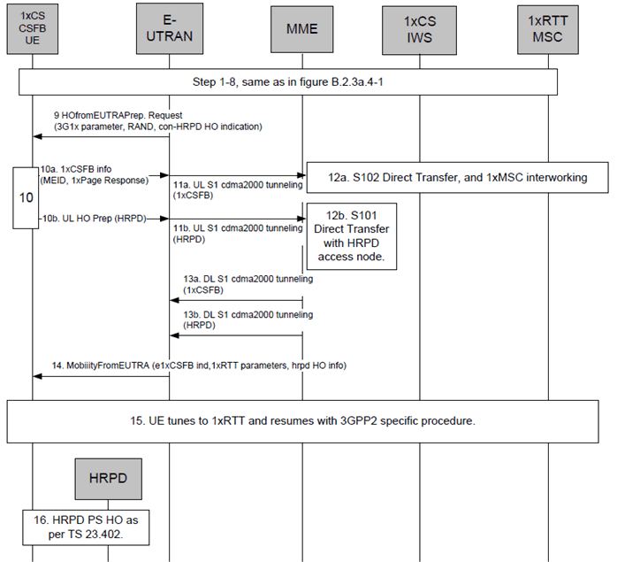
The following Figure describes the mobile terminating call procedures for the enhanced CS Fallback to 1xRTT with concurrent optimised PS handover, in the normal case. Clause B.2.3b describes the procedure when the procedure is rejected by the MME. This procedure is not executed for mobile terminated priority 1x CS Fallback. This procedure is not performed when both the network and the UE support enhanced CS Fallback to 1xRTT for dual receiver/transmitter configuration.

Figure B.2.3a.5-1: Enhanced CS fallback to 1xRTT MT Call with concurrent optimised PS handover
(⇒ copy of original 3GPP image)
(⇒ copy of original 3GPP image)
Step 1-8.
Same as steps 1-8 in Figure B.2.3a.4-1. The UE indicates that it supports enhanced CS fallback to 1xRTT procedures and concurrent 1xRTT and HRPD capability. The UE may also be pre-register with HRPD access using procedures defined in clause 9.3.1 of TS 23.402.
Step 9-16.
Same as steps 6 - 13 of Figure B.2.3a.3-1, with the modifications that the 1x message in step 7 of Figure B.2.3a.2-1 provided by the UE to the E-UTRAN is a 1xPage Response message and 1x messages in step 9a of Figure B.2.3a.2-1 (step 14 of Figure B.2.3a.5-1) provided by the E-UTRAN to UE may also contain Alert With Information message to provide caller line Identification and alerting trigger with 1x channel assignment message.
B.2.3a.6 Interaction between enhanced CS Fallback to 1xRTT and optimised PS handover p. 87
For regular optimized PS handover procedure, it is possible that the UE receives 1xRTT CS paging from EPS while optimised PS handover to HRPD is in progress. In this case, UE shall ignore the 1xRTT CS paging locally.
B.2.3b Mobile Originated or Mobile terminated call rejected by the MME |R9| p. 87
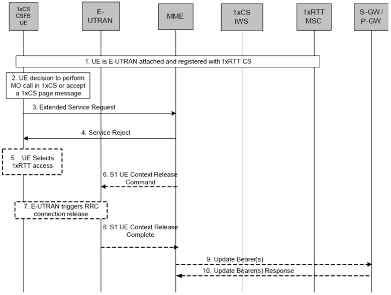
The MME may reject an Extended Service Request either for mobile originated or mobile terminated CSFB. In this case, the following procedure is executed.

Step 1.
Steps 5 - 10 are executed when Service Reject is sent with a reason code which results in the UE selecting 1xRTT access, as specified in TS 24.301.
UE is E-UTRAN attached and pre-registered with 1xRTT CS as defined in clause B.2.1.1.
Step 2.
UE makes a decision to perform a mobile originated CS call or accepts CS paging for the CS Fallback to 1xRTT (Step 6a, Clause 5.2.3).
Step 3.
UE sends an Extended Service Request for mobile originating/mobile terminating 1xCS fallback to the MME.
Step 4.
If the MME decides to reject the Extended Service Request, the MME sends a Service Reject message to the UE.
Step 5.
The UE selects 1xRTT access without waiting for RRC Release.
Step 6.
The MME releases S1 by sending the S1 UE Context Release Command (Cause) message to the eNodeB. Cause value indicates that the release is triggered by CS Fallback procedure.
Step 7.
If the RRC connection is not already released, the E-UTRAN sends a RRC Connection Release message to the UE.
Step 8.
The E-UTRAN confirms the S1 Release by returning an S1 UE Context Release Complete message to the MME.
Step 9-10.
Depending on the reason for rejection, MME may start Suspend Notification:
- Suspend Notification: The S1-U bearers are released and the MME starts the preservation and suspension of non-GBR bearers and the deactivation of GBR bearers towards S-GW and P-GW(s).
- S-GW and P-GW(s) acknowledges the bearer updates Suspend Notification and marks the UE as suspended. The P-GW discards downlink data if the UE is marked as suspended.