Content for TS 23.251 Word version: 18.0.0
A Network Resource Indicator (NRI) allocation examples
A.1 NRI in shared UTRAN/GERAN networks
A.2 Alternatives for NRI split in UTRAN and GERAN
A.3 NRI and CS/PS coordination in GWCN
A.4 CSPS Coordination
A Network Resource Indicator (NRI) allocation examples p. 33
This Annex contains examples for NRI co-ordination for non-supporting UEs in shared networks.
A.1 NRI in shared UTRAN/GERAN networks p. 33
The Network Resource Identifier (NRI) is specified in Rel-5 for Intra Domain Connection of RAN Nodes to Multiple CN nodes (see TS 23.236). NRI is part of the temporary identity TMSI (CS domain) or P-TMSI (PS domain), which is assigned by the serving CN node to the MS. This clause describes NRI usage in MOCN.
Within the shared network NRIs has to be coordinated between the operators at least due to following reasons:
- to avoid redirection or CS/PS un-coordination when the non-supporting UE performs LA/RA update.
- to achieve that correct UE answers to paging (TMSI/P-TMSI shall be unique within shared network).
- to achieve that a non-supporting UE in visited PLMN will not change network due to LA/RA update or Detach/Attach function.
- to achieve that non-supporting UE in visited PLMN remains CS/PS coordinated when the UE moves within shared network.
- to achieve that non-supporting UE in visited PLMN remain registered in the same operators network when the UE moves from dedicated network to a shared network.
- to achieve that non-supporting UE in visited PLMN remains CS/PS coordinated when the UE moves from dedicated network to a shared network.
- to achieve that non-supporting UE in visited PLMN remain registered in the same operators network when the UE moves from dedicated network to a shared network.
- to achieve that non-supporting UE in visited PLMN becomes CS/PS coordinated when the UE moves from EUTRAN to a shared UTRAN or GERAN network.

In the above, one or more of the operators in the shared network may deploy Iu-Flex or A/Gb-Flex between that shared radio access network and their core networks. Additionally, operators may deploy Iu-Flex or A/Gb-Flex within their dedicated core networks. For non-supporting UEs, operator coordination of the CS-NRI and LAI tuple and PS-NRI/MMEC and RAI/TAI tuple is needed not only within the shared network, but also between the shared network and the dedicated networks.
A.2 Alternatives for NRI split in UTRAN and GERAN p. 34
Sharing operators need to coordinate the used NRI, following alternatives are considered:
This could be considered in the case where a network is shared between one big and many small CN operators.
Taking the example configurations mentioned above but changing the TMSI allocation per LA would result in an increase of the addressing space, then the same TMSI value can be used multiple times in the same VLR. More considerations with this TMSI per LA approach can be found in TS 23.236.
- even split of NRI space, 1…3 most significant bits of NRI is used to identify the CN operator.
- individual NRI values used to identify the CN operator.
31 30 29 28 27 26 25 24 23 22 21 20 19 18 17 16 15 14 13 12 11 10 9 8 7 6 5 4 3 2 1 0
CS/PS 'VLR-restart'    CN operator ID Non shared NRI for CN operator internal use.
A calculation for the possible number of subscribers in this scenario is:
- With max 4 sharing CN operators, two most significant bits of NRI is required to identify the CN operator.
- 3 bits are used for the restart counter.
- 5 bits of NRI allows 32 independent NRI values for each CN operator.
- This leaves 20 bits for every MSC that is 1 M non-purged TMSI.
- If more bits are needed for the restart counter or CN operator ID, each additional bit reduces the available TMSI space half.
- The basic configuration allows 32 M TMSI values for each CN operator, a lot of TMSI values are wasted if some sharing partners have substantially less subscribers than others.
- It may not be feasible in large networks that use Iu-Flex or A/Gb-Flex for load balancing (see Annex A, network configuration examples in TS 23.236).
- The number of NRI bits used for CN operator ID may need to be fixed in the initial planning. Otherwise configuration of all existing nodes must be changed when new partners join the shared network.
31 30 29 28 27 26 25 24 23 22 21 20 19 18 17 16 15 14 13 12 11 10 9 8 7 6 5 4 3 2 1 0
CS/PS 'VLR-restart'   Shared NRI space.
- The biggest CN operator who needs more pool areas and TMSI space takes NRI values 32…63, [1xxxxx], this means 32M TMSI values when 4 bit is used for restart counter.
- Rest of shared NRI space is allocated to other CN operators in blocks of 4M TMSI values like NRI = 28 - 31 [0111xx], 24 - 27 [0110xx] …. 0 - 3 [000xx]. Initially gaps can be left between allocated NRI range that can be used for expansion.
- If more bits are needed for the restart counter or NRI, each additional bit reduces the available TMSI space half.
- The initial planning of NRI length should take into account the pool area configurations of all sharing operators.
A.3 NRI and CS/PS coordination in GWCN |R11| p. 35
For GWCN, the BSC and RNC determines a serving CN operator for a non-supporting UE based on the principles defined in clause 4.2.5.3, such that determined CN operator outcome (deterministic outcome) is the same in CS and PS domain.
When source network determines target CN operator in handover and CS fallback, the NRI and MMEC coordination is required as for MOCN (see clause A.1) within the shared network and operator coordination of the CS-NRI and LAI tuple and PS-NRI/MMEC and RAI/TAI tuple between the shared network and the dedicated networks of the sharing partners:
- to achieve that a non-supporting UE in visited PLMN will not change network due to LA/RA update;
- to achieve that non-supporting UE in visited PLMN becomes CS/PS coordinated.
A.4 CSPS Coordination |R13| p. 35
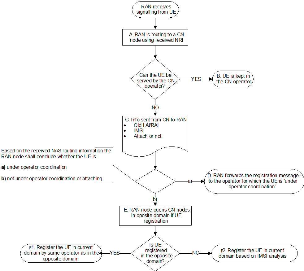
In Figure A.4-1 an example is given how the CSPS coordination can be handled, see also clause 4.2.5.3.

A.
If during execution of step D or E, a registration in the opposite domain occurs, then the RAN node can optionally select as follows:
When the target RAN node receives an idle mode signalling (Attach Request/Routeing Area Update Request/Location Area Update Request messages) from a UE it routes the request to a CN node based on the NRI provided by the UE. For MOCN an operator is thereby selected. For GWCN an operator is selected by the CN node. The RAN stores the NRI received from the UE.
B.
If the UE can be served by the selected CN operator the UE is kept. A 'Redirection Completed' indication shall then be included in the response to the RAN node and the procedure ends. In the following cases the CN operator can serve the UE:
C.
- The UE is a non-roaming subscriber of the selected CN operator.
- The UE is already served by the selected CN operator (e.g. periodic updates or mobility within a pool).
- The RAN node indicates a RAN selected CN operator and the selected CN operator is serving the UE in the opposite domain.
If the UE is not kept by the selected CN operator then 'Redirection Indication' with 'CS/PS coordination Required' and IMSI is included in the response to the RAN node. Old LAI (for the CS domain) or old RAI (for the PS domain) or an indication whether the UE is attaching in the current domain, is also included in the response.
D.
If the UE is under operator coordination, the RAN node selects a core node of the identified operator and forwards the message accordingly. The procedure ends.
However, in conditions valid for step E and if the UE lacks CS registration in the source network (e.g. as with source LTE and no SGs registration) then achieving a successful CS/PS coordination and keeping the same serving operator as in the source network will be dependent upon the access to the information about the source network PS domain registration. For that reason it becomes necessary to check if the UE is registered in the PS domain (see step E) and if so register with that operator also in the CS domain. For example at cell reselection from a source LTE to a target GERAN network without DTM there will, during CS registration, be no registration in the PS domain within the shared target network. Therefore a check must also been done in all possible source networks of the sharing operators otherwise users may become CS/PS uncoordinated. The lack of CS registration in the source network implies an initial CS attach in the target network and therefore step E will be performed.
A similar situation can occur when the UE lacks PS registration (as with no Data roaming for the UE) but for normal cases the UE is already registered in the target shared network in the CS domain when the PS registration occur. Checking in the source networks is then not necessary.
E.
If the UE is not under operator coordination, or if the UE is making an initial attach, the RAN node sends requests to all connected CN nodes or by a possible optimization to one CN node per operator in the opposite domain in the target shared network, to inquire if the UE is served by the opposite domain. To not risk a change of serving operator for cases described in step D (i.e. when attaching to CS domain) then it is also necessary to check in the all MMEs that may hold the UEs context, of the sharing operators, if the UE is registered in the PS domain. Checking the source MMEs is done by relaying requests from target RAN via the CN in the target shared network. However in deployments where these cases are not applicable (e.g. always CS registration in source networks) or when it is sufficient to achieve CS/PS coordination, then the source networks need not to be checked.
F1.
If the UE is registered in the opposite domain then the RAN node retrieves the PLMN of that registered operator and selects the same operator for the current domain. The procedure ends.
F2.
If the UE is not registered in the opposite domain then the RAN node selects operator based on the IMSI analysis. The procedure ends.
- If the UE is registered in the opposite domain and is under operator coordination and is not performing an initial attach, then the RAN node, for both domains, selects serving operator based on the registration information from the opposite domain.
- If the UE is registered in the opposite domain and is not under operator coordination or is attaching, but with regards to the current domain the UE:
- is under operator coordination and is not performing an initial attach, then the RAN node, for both domains, selects serving operator based on the registration information applicable to the current domain.
- is not under operator coordination or is attaching then the RAN node, for both domains, selects serving operator based on IMSI analysis.