Content for TS 23.251 Word version: 18.0.0
7 Example signalling flows
7.1 Network selection
7.1.2 Non-supporting UEs in a GWCN configuration
7.1.3 Supporting UEs in a GWCN configuration
...
...
7 Example signalling flows p. 20
7.1 Network selection p. 20
Signalling flows for manual and automatic network selection in a shared network architecture for successful and unsuccessful registration attempts are presented.
7.1.2 Non-supporting UEs in a GWCN configuration p. 20
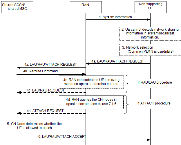
This example shows network selection for a non-supporting UE in a shared UTRAN/GERAN network. The UE is not a subscriber of any of the sharing operators and is under operator coordination. The UE is not coming from E-UTRAN i.e. the UE is not registered in any old MME. The UE is not served by the shared SGSN nor by the shared MSC. After the first registration attempted the operator accepts the UE after CS/PS coordination.

Figure 3: Network selection for a non-supporting UE in a shared UTRAN/GERAN network
(⇒ copy of original 3GPP image)
(⇒ copy of original 3GPP image)
Step 1.
The UE reads the broadcast system information in the shared RAN.
Step 2.
A non-supporting UE cannot decode the shared network information in the broadcast system information. The common PLMN is the only candidate to be considered together with other PLMNs for network selection.
Step 3.
The UE performs network selection among available PLMNs.
Step 4a.
The UE sends an ATTACH REQUEST/ROUTEING AREA UPDATE/LOCATION AREA UPDATE message to the network. The RAN selects CN node based on NRI (valid or invalid) if present or by random selection. A redirect attempt flag is included in the signalling from RAN to Core Network. The signalling from the RAN to the Core Network enables the Core Network to determine that the UE did not select a Core Network operator. The RAN stores the NRI received from the UE.
Step 4b.
A Reroute Command message is sent back to the RAN node with an indication that it is for coordination purposes. The Reroute Command message includes the LAU/RAU /ATTACH REJECT message and the original ATTACH REQUEST/ROUTING AREA UPDATE/LOCATION AREA UPDATE message received from the UE. Included is also IMSI and old LAI (for the CS domain) or old RAI (for the PS domain), or an indication whether the UE is attaching.
Step 4c.
At ROUTEING AREA UPDATE/LOCATION AREA UPDATE the RAN node concludes that the UE is roaming under operator coordination and sends a ROUTEING AREA UPDATE/LOCATION AREA UPDATE to the Core Network. The CN operator selected by the RAN is included in the signalling from RAN to Core Network. IMSI and the redirect attempt flag shall be included.
Step 4d.
At ATTACH REQUEST in PS domain the RAN node queries the MSCs in the CS domain whether the UE (IMSI) is registered at any of the sharing operators in the CS domain. At ATTACH REQUEST in CS domain the RAN node queries the SGSNs in the PS domain whether the UE (IMSI) is registered at any of the sharing operators in the PS domain. For PS domain the SGSNs may need to query all MMEs that may hold the UEs context, refer to clause 7.1.6.
In this example the UE is yet neither registered in the CS domain nor in the PS domain. Based on IMSI analysis the RAN node selects an operator. The RAN node sends a ATTACH REQUEST/ to the Core Network. The CN operator selected by the RAN is included in the signalling from RAN to Core Network. IMSI and the redirect attempt flag shall be included.
Step 5.
The shared SGSN determines whether the UE is allowed to attach.
Step 6.
The shared SGSN sends the appropriate ACCEPT message back to the UE.
7.1.3 Supporting UEs in a GWCN configuration p. 22
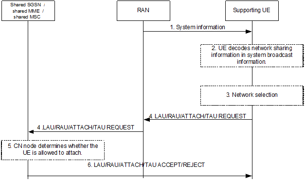
This example shows network selection for a supporting UE in a shared E-UTRAN/UTRAN/GERAN network.

Figure 4: Network selection for a supporting UE in a shared E-UTRAN/UTRAN/GERAN network
(⇒ copy of original 3GPP image)
(⇒ copy of original 3GPP image)
Step 1.
The UE reads the broadcast system information in the shared RAN.
Step 2.
A supporting UE decodes the shared network information and supplies the available core network operator PLMN-ids as candidates to the PLMN selection procedure. Only PLMNs in the Multiple PLMN ID List are candidates for network selection.
Step 3.
The UE performs network selection among available PLMNs.
Step 4.
The UE sends an ATTACH/ROUTEING AREA UPDATE/TRACKING AREA UPDATE/LOCATION AREA UPDATE REQUEST message to the network indicating, to the RAN, the chosen core network operator. The RAN converts the core network 'indicator' into the actual selected PLMN identity and sends this with the ATTACH/ROUTEING AREA UPDATE/TRACKING AREA UPDATE/LOCATION AREA UPDATE REQUEST to the core network.
Step 5.
The shared SGSN determines whether the UE is allowed to attach.
Step 6.
The shared SGSN sends the appropriate ACCEPT/REJECT message back to the UE.