Content for TS 23.231 Word version: 18.0.0
7.2.4 Call Clearing initiated by V-MSC Server
7.2.5 Call clearing received from MGW
7.2.6 Call Clearing procedures towards MGW
7.2.7 Call Clearing for Iu Interface on IP
...
...
7.2.4 Call Clearing initiated by V-MSC Server p. 39
7.2.4.1 Call clearing towards access network p. 39
Call clearing to the UE is performed as described in clause 7.2.2.1.
7.2.4.2 Call clearing towards network side p. 39
Call clearing to the network side is performed as described in clause 7.2.3.2
7.2.4.3 Example Call Flow p. 39
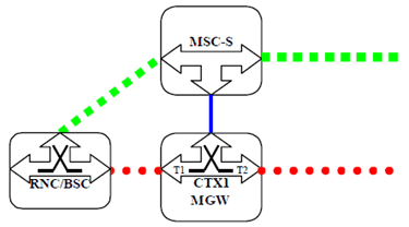
Figure 7.2.4.3.1 shows the network model for a MSC server initiated clearing of an established mobile call. The "squared" line represents the call control signalling. The "dotted" line represents the bearer control signalling (not applicable in A/Gb mode for the A-interface) and the bearer. The MSC server seizes one context with two bearer terminations in the MGW. Bearer termination T1 is used for the bearer towards RNC/BSC and bearer termination T2 is used for the bearer towards succeeding MGW.

Figure 7.2.4.3.1: MSC Server Initiated Call Clearing (Network model)
(⇒ copy of original 3GPP image)
(⇒ copy of original 3GPP image)
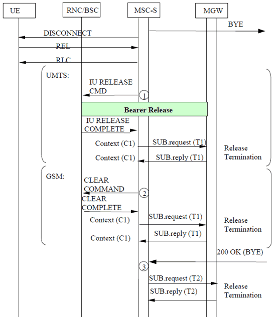
Figure 7.2.4.3.2 shows the message sequence example for the MSC server initiated clearing of an established mobile call. In the example the MSC server initiates call clearing of the network side and the access side. After the call clearing towards the UE and the release of the radio resource have been completed the MSC server requests release of the access side bearer termination. Once the preceding/succeeding node has indicated that call clearing has been completed, the MSC server requests the MGW to release the network side bearer termination.

Figure 7.2.4.3.2: MSC Server Initiated Call Clearing (message sequence chart)
(⇒ copy of original 3GPP image)
(⇒ copy of original 3GPP image)
7.2.5 Call clearing received from MGW p. 40
7.2.5.1 Bearer released on the access side p. 40
After the MSC server has received the Bearer Released procedure from the MGW on the access side, the MSC server shall release the access resources as described in clause 7.2.2.1. If the call is already established towards the network side, call clearing to the network side is performed as described in clause 7.2.3.2.
7.2.5.2 Bearer released on the network side p. 40
After the MSC server has received the Bearer Released procedure from the MGW on the network side, the MSC server shall clear the call to the network side as described in clause 7.2.3.2, and clear the call to the UE as described in clause 7.2.2.1.
7.2.5.3 Example Call Flow p. 40
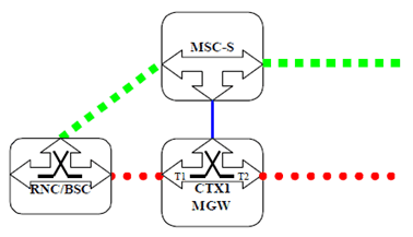
Figure 7.2.5.3.1 shows the network model for an MGW initiated clearing of an established mobile call. The "squared" line represents the call control signalling. The "dotted" line represents the bearer control signalling (not applicable in A/Gb mode for the A-interface) and the bearer. The MSC server seizes one context with two bearer terminations in the MGW. Bearer termination T1 is used for the bearer towards RNC/BSC and bearer termination T2 is used for the bearer towards succeeding MGW.

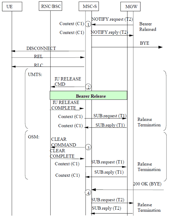
Figure 7.2.5.3.2 shows the message sequence example for the MGW initiated clearing of an established mobile call. After the MSC server is notified that the MGW has released the network side bearer, the MSC server initiates call clearing of the network side and the access side. After the call clearing towards the UE and the radio resource release have been completed the MSC server requests release of the access side bearer termination. Once the preceding/succeeding node has indicated that call clearing has been completed, the MSC server requests the release of the network side bearer termination.

Figure 7.2.5.3.2: MGW Initiated Call Clearing (message sequence chart)
(⇒ copy of original 3GPP image)
(⇒ copy of original 3GPP image)
7.2.6 Call Clearing procedures towards MGW p. 42
The MSC server shall release any network side MGW allocated resources reserved for the call. If any resources were seized in the MGW the MSC server shall use the Release Termination procedure to indicate to the MGW to remove the bearer termination.
7.2.7 Call Clearing for Iu Interface on IP p. 42
Procedures for Call Clearing where the Iu Interface is on IP are as described in clauses through 7.2.2 to 7.2.6.
For Iu Interface on IP, the Release Termination procedure for IP is used to clear the Access side bearer termination.