Content for TS 23.231 Word version: 18.0.0
6 Call Establishment
6.1 Basic Mobile Originating Call
6.1.1 Basic Mobile Originating Call Establishment with immediate MGW selection
6.1.1.1 General
6.1.1.2 MGW selection
6.1.1.3 Initial INVITE message
6.1.1.4 Network side bearer establishment
6.1.1.5 Access bearer assignment
6.1.1.6 Framing protocol initialisation
6.1.1.7 Through-Connection
6.1.1.8 Confirmation of bearer establishment
6.1.1.9 Interworking function
6.1.1.10 Codec handling
6.1.1.11 Voice Processing function
6.1.1.12 Failure handling in MSC server
6.1.1.13 Example
...
...
6 Call Establishment p. 19
6.1 Basic Mobile Originating Call p. 19
6.1.1 Basic Mobile Originating Call Establishment with immediate MGW selection p. 19
6.1.1.1 General p. 19
The mobile originating call shall be established in accordance with TS 23.108. The following clauses describe the additional requirements for the SIP-I based CS core network. The Offer/Answer Procedures of the Session Description Protocol (SDP) for media negotiation shall be applied as specified in TS 29.231.
If multiple speech codecs are offered, Out of Band Transcoder Control (OoBTC) procedures shall be applied by the Originating MSC server in accordance with TS 23.153. Otherwise for speech calls only the default PCM speech codec shall be signalled in an SDP offer; auxiliary payload types such as the Telephony Event RTP payload type may be included in addition. The handling of such auxiliary payload types is described in specific clauses (e.g. DTMF is described in clause 14.4).
For data calls the procedures in TS 29.007 are applicable.
6.1.1.2 MGW selection p. 19
The MSC server shall select an MGW for the bearer connection before it performs the access bearer assignment or the network side connection point reservation. This shall happen before sending the INVITE message.
6.1.1.3 Initial INVITE message p. 19
The MSC server shall send the initial INVITE message before or after the access bearer assignment is completed. The MSC server shall provide the supported SDP (e.g. core network side user plane IP transport address and port, codec(s), RTP telephony event) to the succeeding node in the initial INVITE message. The initial INVITE message shall encapsulate the IAM message. If the access bearer assignment has not been completed, the MSC server shall indicate that the local precondition has not been met.
6.1.1.4 Network side bearer establishment p. 19
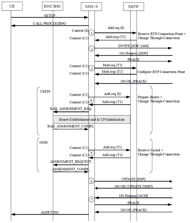
The MSC server shall select the codec for this connection and request the MGW to select and provide the IP transport address and port for the network side bearer connection before sending the INVITE message. If OoBTC is supported, the selected codec may be the preferred codec for this connection. The MSC server shall use the Reserve RTP Connection Point procedure (bullet 1 in Figure 6.1.1.13.2-1). Within this procedure, the MSC server shall indicate the codec and any additional payload types (e.g. RTP Telephony Event) and shall request a local IP address and UDP port from the MGW. The MSC server may indicate that the IP interface type is for Nb over IP with SIP-I based Nc. The local IP address and UDP port are used by the MGW to receive user plane data from the succeeding MGW.
Support and selection of CS Data payload types is described in TS 29.007.
The MGW shall reply to the MSC server with the selected local IP address and UDP port.
The MSC server shall send this information in the INVITE (bullet 2 in Figure 6.1.1.13.2-1) to the succeeding node.
After the succeeding node has provided the SDP answer, the MSC server shall use the Configure RTP Connection Point procedure to request the MGW to configure the remote address, codec and any additional negotiated payload types (e.g. RTP Telephony Event) (bullet 3 in Figure 6.1.1.13.2-1) of the bearer termination. If OoBTC is supported, the Configure RTP Connection Point procedure may amend the selected codec for this connection if different from the codec sent in the previous Reserve RTP Connection Point procedure (bullet 1 in Figure 6.1.1.13.2-1). The Configure RTP Connection Point procedure may indicate that the IP interface type is for Nb over IP with SIP-I based Nc.
6.1.1.5 Access bearer assignment p. 20
The access bearer assignment is defined in the clause 6.1.1.4 of TS 23.205.
6.1.1.6 Framing protocol initialisation p. 20
There is no specific framing protocol initialisation in the SIP-I based CS network. The MGW terminates the Iu Framing Protocol towards the Iu interface and will receive an Iu UP Initialisation from an Iu-CS interface connected to the radio interface and shall process it according to the procedures in TS 25.415 and TS 29.232. No information from the framing protocol initialisation needs to be interworked towards the Nb interface of a SIP-I based CS core network. Information within subsequent Iu UP payload PDUs and RTP PDUs shall be interworked according to the procedures in TS 29.414.
6.1.1.7 Through-Connection p. 20
In combination with the Prepare Bearer or Reserve Circuit procedures, and the Reserve RTP Connection Point or Configure RTP Connection Point procedure, the MSC server should use the Change Through-Connection procedure to request the MGW to configure the bearer terminations so that the bearer is through-connected in the backward direction (bullet 1 or 3 and bullet 4 or 5 in Figure 6.1.1.13.2-1).
For a multimedia call, the MSC may request the MGW to both-way through-connect the bearer using the Change Through-Connection procedure to generate a multimedia CAT (see clause 14.10.1).
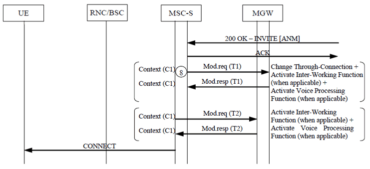
Otherwise when the MSC server receives the answer indication (200 OK(INVITE)), it shall request the MGW to both-way through-connect the bearer using the Change Through-Connection procedure (bullet 8 in Figure 6.1.1.13.2-1), unless the bearer has already been both way through-connected at an earlier stage.
6.1.1.8 Confirmation of bearer establishment p. 20
If the initial INVITE message which was sent to the succeeding node indicated that the local precondition has not been met, the MSC server shall send an UPDATE message indicating that the local preconditions are met when the access bearer assignment has been completed (bullet 6 in Figure 6.1.1.13.2-1).
6.1.1.9 Interworking function p. 20
The MGW may use an interworking function that is based on the PLMN Bearer Capability, TS 24.008, of the bearer termination. The activation of the possible interworking function in both bearer terminations will be requested by the MSC server at reception of the SIP 200 OK (INVITE) response using the Activate Interworking Function procedure (bullet 8 in Figure 6.1.1.13.2-1).
6.1.1.10 Codec handling p. 20
The MGW may include a speech transcoder based upon the speech coding information provided to each bearer termination.
6.1.1.11 Voice Processing function p. 20
A voice processing function (i.e. echo cancellation) located on the MGW may be used to achieve desired acoustic quality on the bearer terminations. The MSC server shall request the activation of voice processing functions in the bearer terminations. For non-speech calls, the MSC server has the ability to instruct the MGW to disable the voice processing functions (bullet 8 in Figure 6.1.1.13.2-2).
6.1.1.12 Failure handling in MSC server p. 20
If any procedure between the MSC server and the MGW has not completed successfully or the MSC server receives a Bearer Released procedure from the MGW, the call shall be cleared as described in clause 7.2.4, visited MSC server initiated call clearing or in clause 7.2.5, MGW initiated call clearing. Alternatively, the MSC server may only release the resources in the MGW that caused the failure, possibly select a new MGW for the bearer connection and continue the call establishment using new resources in the selected MGW.
6.1.1.13 Example p. 21
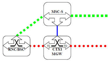
Figure 6.1.1.13.1 shows the network model for the mobile originating call. The "squared" line represents the call control signalling. The "dotted" line represents the bearer control signalling (not applicable in A/Gb mode for the A-interface) and the bearer. The MSC server seizes one context with two terminations in the MGW. The bearer termination T1 is used for the bearer towards the RNC/BSC and the bearer termination T2 is used for the bearer towards the succeeding MGW.


Figure 6.1.1.13.2-1: Basic Mobile Originating Call with early originating access bearer assignment (message sequence chart).
(⇒ copy of original 3GPP image)
(⇒ copy of original 3GPP image)

Figure 6.1.1.13.2-2: Basic Mobile Originating Call with early originating access bearer assignment (message sequence chart).
(⇒ copy of original 3GPP image)
(⇒ copy of original 3GPP image)