Content for TS 23.214 Word version: 18.0.0
1…
4.3…
5…
5.6…
5.10…
6…
6.3…
6.3.1.2
6.3.1.3…
6.3.1.6…
6.3.2…
6.3.3…
6.3.3.4…
6.3.3.7…
6.3.4…
6.3.4.2…
6.3.4.2.2
6.3.4.3
6.4…
7…
1 Scope
2 References
3 Definitions and abbreviations
3.1 Definitions
3.2 Abbreviations
4 Architecture model and concepts
4.1 General concepts
4.2 Architecture reference model
4.2.1 Non-roaming and roaming architectures
4.2.2 Combined SGW/PGW architecture
4.2.3 Reference points
...
...
1 Scope p. 7
The present document specifies the overall stage 2 level functionality for control and user plane separation of EPC's SGW, PGW and TDF. This enables a flexible placement of the separated control plane and user plane functions for supporting diverse deployment scenarios (e.g. central or distributed user plane function) without affecting the overall functionality provided by these EPC entities.
2 References p. 7
The following documents contain provisions which, through reference in this text, constitute provisions of the present document.
- References are either specific (identified by date of publication, edition number, version number, etc.) or non-specific.
- For a specific reference, subsequent revisions do not apply.
- For a non-specific reference, the latest version applies. In the case of a reference to a 3GPP document (including a GSM document), a non-specific reference implicitly refers to the latest version of that document in the same Release as the present document.
[1]
TR 21.905: "Vocabulary for 3GPP Specifications".
[2]
TS 23.401: "General Packet Radio Service (GPRS) enhancements for Evolved Universal Terrestrial Radio Access Network (E-UTRAN) access".
[3]
TS 23.203: "Policy and charging control architecture".
[4]
TS 23.402: "Architecture enhancements for non-3GPP accesses".
[5]
TS 23.060: "General Packet Radio Service (GPRS); Service description; Stage 2".
[6]
TS 29.060: "GPRS Tunnelling Protocol (GTP) across the Gn and Gp interface".
[7]
TS 29.274: "3GPP Evolved Packet System (EPS); Evolved General Packet Radio Service (GPRS) Tunnelling Protocol for Control plane (GTPv2-C); Stage 3".
[8]
TS 32.251: "Telecommunication management; Charging management; Packet Switched (PS) domain charging".
[9]
TS 32.240: "Charging architecture and principles".
[10]
TS 33.107: "3G security; Lawful interception architecture and functions".
[11]
TS 29.212: "Policy and Charging Control (PCC); Reference points".
[12]
TS 29.244: "Interface between the Control Plane and the User Plane of EPC Nodes; Stage 3".
[13]
TS 28.708: "Telecommunication management; Evolved Packet Core (EPC) Network Resource Model (NRM) Integration Reference Point (IRP); Information Service (IS)".
[14]
TS 29.061: "Interworking between the Public Land Mobile Network (PLMN) supporting packet based services and Packet Data Networks (PDN)".
3 Definitions and abbreviations p. 8
3.1 Definitions p. 8
For the purposes of the present document, the terms and definitions given in TR 21.905, TS 23.401, TS 23.203 and the following apply. A term defined in the present document takes precedence over the definition of the same term, if any, in TR 21.905.
F-TEID:
as defined in clause 8.22 of TS 29.274.
F-TEIDu:
The F-TEID of a GTP-u tunnel.
3.2 Abbreviations p. 8
For the purposes of the present document, the abbreviations given in TR 21.905, TS 23.401, TS 23.203 and the following apply. An abbreviation defined in the present document takes precedence over the definition of the same abbreviation, if any, in TR 21.905.
CP function
Control Plane function
PGW
PDN Gateway
PGW-C
PDN Gateway Control plane function
PGW-U
PDN Gateway User plane function
SGW
Serving Gateway
SGW-C
Serving Gateway Control plane function
SGW-U
Serving Gateway User plane function
TDF
Traffic Detection Function
TDF-C
Traffic Detection Function Control plane function
TDF-U
Traffic Detection Function User plane function
UP function
User Plane function
4 Architecture model and concepts p. 8
4.1 General concepts p. 8
The architecture and functionality for control and user plane separation of SGW, PGW and TDF is based on the following concepts:
- Interworking with networks not applying control and user plane separation is possible (i.e. in case of roaming scenarios);
- Split network entities can interwork with network entities that are not split within the same network;
- Split network entities have no requirement to update UE, and Radio Access Network;
- The SGW/PGW selection function of the MME/ePDG/TWAN described in TS 23.401 and TS 23.402 is used for the selection of the respective CP function;
- The configuration based mechanism (in PGW or PCRF) described in TS 23.203 is used for the selection of the CP function of the TDF;
- A CP function can interface with one or more UP functions (e.g. to enable independent scalability of CP functions and UP functions).
4.2 Architecture reference model p. 9
4.2.1 Non-roaming and roaming architectures p. 9
This clause defines the complementary aspects of the architecture reference models specified in clause 4.2 of TS 23.401 and clauses 4.2.2 and 4.2.3 of TS 23.402 for GTP-based interfaces when SGW, PGW and TDF control and user planes are separated.
For S2a, S2b, S5 and S8 reference points, this architecture reference model is only supported with GTP-based interfaces. PMIP-based interfaces and S2c interface are not supported.
Figure 4.2.1-1 shows the architecture reference model in the case of separation between control plane and user plane. This architecture reference model covers non-roaming as well as home routed and local breakout roaming scenarios.
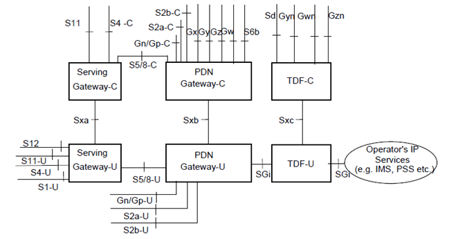
Figure 4.2.1-1: Architecture reference model with separation of user plane and control plane for non-roaming and roaming scenarios
(⇒ copy of original 3GPP image)
(⇒ copy of original 3GPP image)
4.2.2 Combined SGW/PGW architecture p. 9
The usage of a combined SGW/PGW documented in TS 23.401 remains possible in a deployment with separated control and user planes. This is enabled by supporting an Sx interface with a common parameter structure for non-combined and combined cases. Figure 4.2.2-1 shows the architecture reference model for a combined SGW/PGW in the case of separation between control plane and user plane.
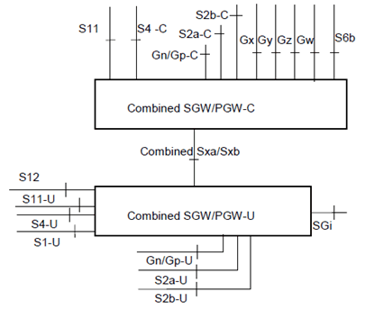
Figure 4.2.2-1: Architecture reference model with separation of user plane and control plane for a combined SGW/PGW
(⇒ copy of original 3GPP image)
(⇒ copy of original 3GPP image)
4.2.3 Reference points p. 10
This clause defines the complementary reference points of the architecture reference models specified in clause 4.2 of TS 23.401 and clauses 4.2.2 and 4.2.3 of TS 23.402 for GTP-based interfaces when SGW, PGW and TDF control and user planes are separated.
The reference points added to the reference points defined in TS 23.401, TS 23.402 and TS 23.203 are the following ones:
Sxa:
Reference point between SGW-C and SGW-U.
Sxb:
Reference point between PGW-C and PGW-U.
Sxc:
Reference point between TDF-C and TDF-U.
![]()
![]()
![]()