Content for TS 23.167 Word version: 19.0.0
D Examples of call flows according to NENA I2 recommendations
D.1 ECS redirecting IMS emergency call
D.2 ECS routes the emergency call to the gateway with record route
...
...
D Examples of call flows according to NENA I2 recommendations p. 43
This clause provides the examples of call flows according to NENA I2 recommendations [17].
D.1 ECS redirecting IMS emergency call p. 43

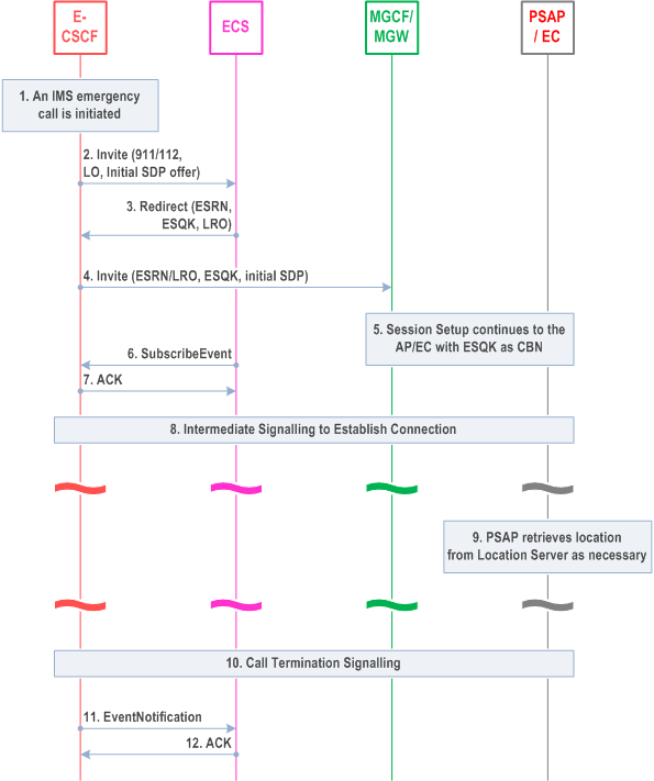
This flow is supported by the procedures in clause 7.3, where the E-CSCF need not enquire the LRF for location information. Additional steps defined here are standard SIP methods, but not defined in this specification.
Detailed description of the procedure:
Step 1.
An IMS emergency call is initiated.
Step 2.
The E-CSCF sends an Invite message with 911 or other well-known emergency number as the dialled number, the UE's location information in a Location Object (LO) if available and the UE's media capabilities encapsulated in a SDP payload, to the ECS.
Step 3.
Based on the received Location Object (LO), the ECS will determine to which PSAP/EC the call should be routed and allocate an ESQK from the ESQK pool associated with that particular PSAP/EC. The ECS then will format a SIP response with the retrieved ESRN/ESQK in the Contact fields to redirect the emergency call.
Step 4.
The IMS Core uses the ESRN/ESQK received in the call redirect message to format an INVITE message properly and sends it to the MGCF/MGW. A P-Asserted-Identity field may be inserted in the INVITE message, it contains either an ESQK or the CBN.
Step 5.
The emergency call setup continues with the PSAP/EC.
Step 6.
The ECS initiates a subscription at the IMS Core to request a notification of call termination of the emergency call.
Step 7.
An acknowledgement is returned.
Step 8.
The emergency session establishment signalling continues.
Step 9.
The PSAP retrieves location from the ECS.
Step 10.
The emergency session is released.
Step 11.
The IMS Core sends an Event Notification message to the ECS with an Event indicating that the 911 call has been terminated. At this time, the ESQK allocated to the emergency session can be released.
Step 12.
An acknowledgement is returned to the IMS Core.
D.2 ECS routes the emergency call to the gateway with record route p. 45

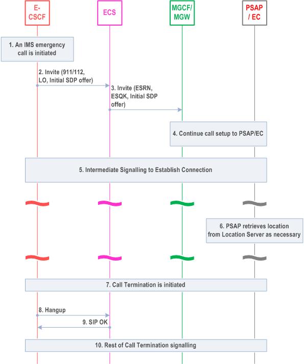
This flow is supported by the procedures in clause 7.3, where the E-CSCF need not enquire the LRF for location information.
Detailed description of the procedure:
Step 1.
An IMS emergency call is initiated.
Step 2.
The E-CSCF sends an Invite message with 911 or other well-known emergency number as the dialled number, the UE's location information in a Location Object (LO) if available and the UE's media capabilities encapsulated in a SDP payload, to the ECS.
Step 3.
Based on the received Location Object (LO), the ECS will determine to which PSAP/EC the call should be routed and allocate an ESQK from the ESQK pool associated with that particular PSAP/EC. The ECS then re-issues an Invite to an appropriate MGCF/MGW with the ESRN/LRO, ESQK and a record route indication. or the call to be routed to PSAP the P-Asserted-Identity contains ESQK, A P-Asserted-Identity field may be inserted in the INVITE message, f for the call to be routed to other emergency answering centre the P-Asserted-Identity contains the CBN.
Step 4.
The emergency call setup continues with the PSAP/EC.
Step 5.
The emergency session establishment signalling continues.
Step 6.
The PSAP retrieves location from the ECS.
Step 7.
Either the caller or PSAP initiates the call termination signalling.
Step 8.
The E-CSCF or MGCF/MGW forwards the hang-up message to the ECS. At this time, the ESQK allocated to the emergency session can be released.
Step 9.
The ECS sends an OK to the E-CSCF or MGCF/MGW.
Step 10.
The call termination signalling continues.