Content for TS 23.041 Word version: 18.6.0
1…
2
3…
4…
6…
9…
9.1.3.3
9.1.3.4…
9.1.3.5…
9.1.4…
9.2…
9.2.10…
9.2.21…
9.3…
9.3.20…
9.3.40…
9.4…
9.4.2…
9.5
9A…
10…
B…
3 Network Architecture
3.0 General
3.1 GSM Network Architecture
3.2 UMTS Network Architecture
3.3 EPS Network Architecture
3.4 5GS Network Architecture
...
...
3 Network Architecture p. 11
3.0 General |R11| p. 11
The chosen network architectures differ for GSM, UMTS, EPS, and 5GS. In clause 3.1 the GSM network architecture is descripted, in clause 3.2 the UMTS network architecture, in clause 3.3 the EPS network architecture, and in clause 3.4 the 5GS network architecture.
3.1 GSM Network Architecture p. 11
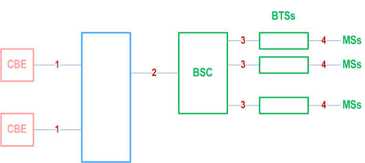
The basic network structure of CBS is depicted by Figure 1.

- message transfer on link 1 is outside the scope of 3GPP specifications;
- message transfer on link 2 is described in clause 9.1;
- message transfer on link 3 is described in TS 48.058;
- message transfer on link 4 is described in TS 44.012 and the timing of messages transferred on link 4 is described in TS 45.002.
3.2 UMTS Network Architecture p. 12
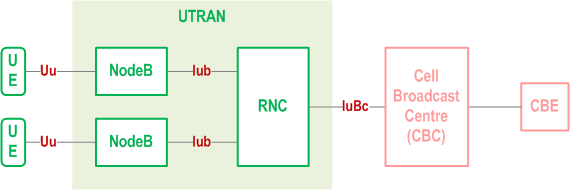
The basic network structure of CBS is depicted by Figure 2.

The basic network structure replaces the GSM BSS with the UTRAN containing the RNC and the Node B. The cell broadcast centre (CBC) is part of the core network and connected to a routing node e.g. a 3G SGSN via the Bc reference point. Thus the CBC can reach every RNC via the user plane of the Iu interface. On the logical interface between the CBC and the RNC protocol is described in TS 25.419. The other UTRAN related interfaces are described in the according UTRAN specifications based on the 3GPP TR 25.925 [21]. Based on this architecture and the current requirements for cell broadcast the core network elements like MSC, VLR, HLR etc are not involved for the service delivery.
The CBE and the interface between CBE and CBC are out of scope of 3GPP specifications.
3GPP TS 23.251 specifies additional requirements for providing CBS in shared UTRAN.
3.3 EPS Network Architecture |R8| p. 13
The basic network structure of PWS architecture in E-UTRAN is depicted by Figure 3.3-1.

The cell broadcast centre (CBC) is part of the core network and connected to the MME via the SBc reference point. The interface between the CBC and the MME is described in TS 29.168 and the interface between the MME and the eNodeB is described in TS 36.413.
The CBE and the interface between CBE and CBC are out of scope of 3GPP specifications.
3GPP TS 23.251 specifies additional requirements for providing PWS in shared E-UTRAN.
3.4 5GS Network Architecture |R14| p. 13
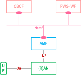
Figure 3.4-1, Figure 3.4-2 and Figure 3.4-3 depict the basic network structure of 5GS PWS architecture.
Figure 3.4-1 depicts the 5GS PWS system architecture, using service-based interfaces between CBCF and AMF, showing how the network functions interact with each other. This option is further described in clause 4 to clause 8. The service-based interfaces are further described in clause 9A.

Figure 3.4-2 depicts the basic network structure of 5GS PWS architecture using the reference point representation showing how the network functions interact with each other when no PWS-IWF is used. This option is further described in clause 4 to clause 8.

Figure 3.4-3 depicts the basic network structure of 5GS PWS architecture using the reference point representation showing how the network functions interact with each other when PWS-IWF is used. This option is further described in Annex B.

The 5GS PWS architecture contains the following service-based interface:
Namf:
The 5GS PWS architecture contains the following reference points:
Service-based interface exhibited by AMF.
N2:
The CBE and the interface between CBE and CBC are out of scope of 3GPP specifications.
In shared NG-RAN, PWS is provided via a single common CBCF which connects to the shared NG-RAN via one or more AMFs, or via a single common CBC which connects to the shared NG-RAN via one or more AMFs and one or more PWS-IWFs. The deployment and configuration of the common CBCF or the common CBC is per agreement between the sharing operators. The sharing operators need to coordinate PWS between each other.
Reference point between the NG-RAN and the AMF.
N50:
Reference point between the AMF and the CBCF or between the AMF and the PWS-IWF.
SBc:
Reference point between the PWS-IWF and the CBC.