Content for TS 23.040 Word version: 18.0.0
0…
3…
3.3…
4…
8…
9…
9.2…
9.2.2.2…
9.2.2.3…
9.2.3…
9.2.3.12…
9.2.3.24
9.2.3.24.1…
9.2.3.24.10…
9.2.3.24.10.1.12…
9.2.3.24.10.2…
9.2.3.24.11…
9.2.3.25…
9.3…
10…
10.1.1…
10.1.3…
10.1.5…
10.1.7…
10.1.9…
10.1.11…
10.1.13…
10.1.15…
10.1.17…
10.2
10.2.1…
10.2.3…
10.2.5…
10.2.7…
10.3
11…
A…
C
C.1…
C.3…
C.5…
C.7…
C.9…
C.11…
C.13…
C.15…
D…
E…
F…
G…
G.2…
G.6
G.7
H…
I…
J…
K…
G WVG (Wireless Vector Graphics) data format
G.1 Introduction
G.1.1 Standard and Character Size WVG elements
G.1.2 Compression methods
G.1.3 Coordinate Systems
G.1.3.1 Compact Coordinate System
G.1.3.2 Flat Coordinate System
G.1.3.3 Coordinate values
G.1.4 Color schemes
G.1.5 Rendering model
...
...
G (Normative) WVG (Wireless Vector Graphics) data format |R5| p. 175
WVG (Wireless Vector Graphics) is a compact binary data format for vector graphics. WVG data is represented by a bit stream, composed of a header, codec parameters and graphical elements. The bit representation of the drawing and contained graphical elements is designed such that the bit stream can be optimized for smallest possible size.
G.1 Introduction p. 175
G.1.1 Standard and Character Size WVG elements p. 175
A Standard WVG element is defined by the complete WVG specification. Using a set of the WVG specification with a set of default values, a simplified vector graphics can be used to represent a simple and small vector graphics or glyph. Character Size WVG elements can be included in normal text to represent a handwritten character or symbols that are not supported by character coding system and the font library.
G.1.2 Compression methods p. 175
A combination of compression methods is used in the WVG to achieve the best compression ratio for simple vector graphics and animations. They include:
- switchable linear or non-linear coordination system: when graphical elements in a drawing are not evenly distributed, the representation of coordinates can be optimized using a non-linear coordinate system (uneven coordinates)
- bit packing: variable number of bits to represent a number. The number of bits used in WVG can vary from 1 bit to 16 bits.
- local envelope: use a dedicated coordinate system to describe elements in a small area using relatively small coordinate numbers
- variable resolution: in coordinates, sizes, angles, scale and etc, different resolutions can be used for a graphical element to save the number of bits needed for representing a value.
- palettes: color and element ID can be mapped using a palette defined in the drawing header. This also saves the number of bits for representing a color value and an element ID.
- default values: many values can be omitted to use default values. E.g. when no color scheme is defined, the data describes a mono drawing
- default animation timing: in addition to standard time based animation, WVG uses a simplified animation model. In Simple Animation mode, no timing is needed for describing animations. Instead, a cycle is defined to describe the timing for these animations.
G.1.3 Coordinate Systems p. 176
There are two coordinate systems used in WVG, namely Compact Coordinate System and Flat Coordinate System.
G.1.3.1 Compact Coordinate System p. 176
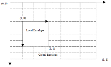
In compact coordinate system, a drawing area is defined as rectangle area called envelope. There are two types of envelopes, global envelope and local envelope. The global envelope is a base area in which the drawing is contained. There is only one global envelope. A local envelope is a square area completely or partially within the global envelope. There is no specific global envelope size specified in the data format. The physical display size is decided at rendering time.
The aspect ratio and orientation are defined in the data header and should be maintained when the drawing is displayed.
Aspect ratios include 1:1, 4:3, 16:9 up to 1024: 729 (height:width), in both portrait and landscape orientation. Aspect ratio for Characters Size WVG elements only has landscape orientation.

In Compact Coordinate System, coordinates are restricted to certain positions which are the cross points of a grid. The grid is defined in the WVG data header, set by a group of parameters. The grid lines along with x axis or y axis may be unevenly distributed.
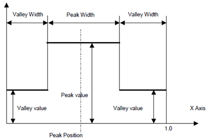
The global grid can be described using a curve shown above.

There are one peak and two valleys in the curve. The definition of the curve is:
 Where Xk is the position of the kth grid line, where n is total number of grid lines. d(x) is the curve function described in the present document.
In standard WVG, the curve parameters are preset as follows.
Variable parameters:
- peak position: the central position of a peak;
- peak value: a value equal or larger than 1,0;
- peak width: a value less than 1,0.

- number of grid lines: 15, 31, 63 or 127;
- peak value: 1,0, 1,5, 2,0 and 2,5;
- peak position: 13 options from 0,0 (0/12), 0,083333 (1/12), 0,166667 (2/12) to 1,0 (12/12);
- peak width: 0,3, 0,4, 0.5 and 0,6.
- peak width: 0,4.
- number of grid lines: 7, 15, 31 or 63;
- peak value: 1,0 or 1,5;
- peak position: 0,3333 (1/3), 0,5, 0,6667 (2/3).
G.1.3.2 Flat Coordinate System p. 178
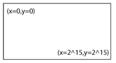
The Flat Coordinate System is a 16 bit signed coordinate system with the top left coordinate of the screen being defined as (x=0,y=0) and the bottom right coordinate being described as (x=2^15, y = 2^15). Note that this expresses the dynamic range of the coordinate system, however it does not mean that all drawings are of this size.

G.1.3.3 Coordinate values p. 178
Coordinate values may be represented using two methods: absolute coordinate and relative coordinate.
Absolute Coordinate:
an absolute coordinate is a pair of x and y coordinate number. In WVG Compact Coordinate System, absolute coordinate values are the coordinate grid line numbers and are always positive.
Relative Coordinate:
the relative coordinate is used only in lines and transform. If the start point is defined by an absolute coordinate, subsequent points can be described by relative coordinates, which are relative grid units from the previous point. A relative coordinate is signed, and it may be positive or negative. A relative coordinate may be used in both global and local coordinate systems. A relative coordinate may exceed the scope of the local envelope that defines the start point of the line.
G.1.4 Color schemes p. 178
WVG supports the following color schemes.
- Black and white (2 Colors): black and white color.
- 2-bit grayscales: four grayscales are defined as (0,0,0), (85,85,85), (170,170,170) and (255,255,255) in 24-bit RGB color format.
- 4 default colors.
- 6-bit RGB color: it is similar to 24-bit RGB color definition but uses only 2 bits to represent a single color, in which value 0, 1, 2 and 3 represent 8-bit color value 0, 85, 170 and 255 respectively.
- 6-bit RGB color using 2nd palette.
- 8-bit websafe color.
- 12-bit and 24-bit RGB color.
G.1.5 Rendering model p. 179
WVG uses painter model. The elements appears in the later position in the WVG bit stream will overrides the overlapped portion of the elements which appear in the front in the bit stream.