Content for TR 22.848 Word version: 19.0.0
5.2 Use case on Interconnect between SNPNs
5.2.1 Description
5.2.2 Pre-conditions
5.2.3 Service Flows
5.2.4 Post-conditions
5.2.5 Existing features partly or fully covering the use case functionality
5.2.6 Potential New Requirements needed to support the use case
...
...
5.2 Use case on Interconnect between SNPNs p. 9
5.2.1 Description p. 9
SNPNs are expected to be deployed in government offices, banks, hotels, hospitals, schools, etc. in an administrative area. Each SNPN exposes its localized services.
Interconnect between different SNPN, subject to appropriate agreements, can make access to localized services seamless. Namely, when SNPNs, deployed by different administrations, are interconnected with each other and their services exposed, local services of one SNPN can be accessed via the other SNPNs. For example, a medical service, instantiated on a SNPN deployed in a central hospital, can be exposed to distributed family clinics. Also, an identity created in a family clinic can be utilized at the central hospital.
A benefit of the interconnect between SNPN can also be seen when a disaster happens, where PLMN-based service become unavailable due to congestion caused by the disaster in the area. On the other hand, as SNPNs are basically isolated from the PLMNs, the SNPNs are not impacted by the congestion in the PLMNs. This is, for example, good for city governments because the city government can keep their public services over the interconnected SNPNs.
In the context of interconnected SNPNs, identity providers authenticate individual users in SNPNs and authorize them to consume services on the SNPNs.

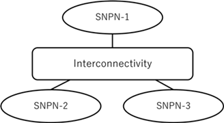
Assume that multiple SNPNs, for example, SNPN-1, SNPN-2 and SNPN-3, are deployed at different places. In Figure 5.2.1-2, SNPN-1 is the central SNPN and SNPN-2 and SNPN-3 are branches. It is also expected that there is a backbone/transport network to provide interconnectivity among SNPN-1, SNPN-2 and SNPN-3. The backbone network could be a public network (e.g. The internet) or a private/ managed network (e.g. enterprise network owning the SNPNs).

Following interconnectivity can be considered but the list is not exhaustive.
- Point-to-point interconnectivity that connects a point with another point.
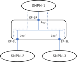
- Hub & Spoke interconnectivity that connects a root point with other leaf points.
- Gateway interconnectivity that connects multiple points with other multiple points with a full mesh topology

In a case where hub & spoke interconnectivity in Figure 5.2.1-4 is deployed among SNPN-1, SNPN-2 and SNPN-3, internal traffic among interconnectivity endpoints transferred via the root endpoint. For example, a central hospital provides SNPN-1, whereas family clinics #2 and #3 are consumers of SNPN-2 and SNPN-3, respectively. As assumed that SNPN-1 is the central SNPN, SNPN-1 can also provide identity services. For example, the internal traffic from EP-3L hosting SNPN-3 is transferred to SNPN-1 via EP-1R and then SNPN-1 routes the traffic from EP-1R to EP-2L hosting SNPN-2. It should be noted that an identity provider service could also be located in the external data network connecting to SNPN-1.

In a case where gateway interconnectivity in Figure 5.2.1-5 is deployed among SNPN-1, SNPN-2 and SNPN-3, internal traffic among interconnectivity endpoints transferred between each interconnectivity endpoint. Each SNPN can communicate with each other via the gateway interconnect service. For example, services such as an identity provider service could directly be interfaced with the interconnectivity. In this case, the identity provider service can seamlessly be consumed via any SNPNs and an identity assigned with a user can be authenticated and authorized in any SNPN.

An interconnectivity (e.g. point-to-point, hub & spoke, gateway, etc.) is, for example, designed by a producer of the interconnect. The interconnect describes a collection of interconnectivity endpoints and how to access to the interconnectivity endpoints from SNPN-1, SNPN-2 and SNPN-3.
In general, the interconnect information is provided by a producer to consumers. For example, there is a case where the backbone network operator is a producer of the interconnect and SNPN-1, SNPN-2 and SNPN-3 are consumers. In another case, SNPN-1 is a producer of the interconnect and SNPN-2 and SNPN-3 are consumers. The interconnect information may be exchanged between the producer and consumers.
5.2.2 Pre-conditions p. 11
It is assumed that a hub & spoke model is deployed in a central hospital and family clinics for this service flow. SNPN-1 is the root, deployed in central hospital and SNPN-2 and SNPN-3 are leaves, deployed in family clinics #2 and #3, respectively. SNPN-1, SNPN-2 and SNPN-3 are connected to the backbone network and they are at least IP reachable with each other. As such, this use case discusses a case of managed interconnect between different SNPNs.
5.2.3 Service Flows p. 12
- An interconnect for a hub & spoke model is designed by a producer of SNPN-1, deployed in the central hospital. The interconnect describes a collection of interconnectivity endpoints for the root and branches and how to access to the interconnectivity endpoints from SNPN-1, SNPN-2 and SNPN-3.
- The interconnect provided by SNPN-1 to SNPNs deployed in the family clinics, i.e. SNPN-2 and SNPN-3.
- The management system of SNPN-1 selects an endpoint within 5GS of SNPN-1 to an interconnectivity endpoint (root) and then prepares an access link to the interconnectivity endpoint.
- The management system of SNPN-2 selects an endpoint within 5GS of SNPN-2 to an interconnectivity endpoint (leaf) and then prepares an access link to the interconnectivity endpoint.
- The management system of SNPN-3 selects an endpoint within 5GS of SNPN-3 to an interconnectivity endpoint (leaf) and then prepares an access link to the interconnectivity endpoint.
5.2.4 Post-conditions p. 12
The interconnect between SNPN-1, SNPN-2 and SNPN-3 is realised using the selected topology model and 5GS endpoints, and then the SNPNs can exchange data.
5.2.5 Existing features partly or fully covering the use case functionality p. 12
Further existing features that partly or fully cover the use case functionality are FFS.
5.2.6 Potential New Requirements needed to support the use case p. 12
[PR 5.2.6-001]
Subject to SNPNs operators' agreement, the 5G system shall be able to support mechanisms to enable interconnect between standalone non-public networks.
[PR 5.2.6-002]
Subject to SNPNs operators' agreement, the 5G system shall be able to support mechanisms for a selection of 5GS endpoints for SNPNs' interconnect.