Content for TR 21.917 Word version: 17.0.1
0…
5…
5.2
6…
6.3…
6.3.2…
6.3.3…
6.3.4…
7…
7.4…
8…
9…
10…
11…
11.9…
12…
13…
14…
15…
15.6…
16…
17…
18…
18.10…
19…
7.4 Support of Enhanced Industrial IoT (IIoT)
7.5 Support of reduced capability NR devices
7.6 IoT and 5G access via Satellite/Non-Terrestrial (NTN) link
7.7 Charging enhancement for URLLC and CIoT
7.8 Messaging in 5G
...
...
7.4 Support of Enhanced Industrial IoT (IIoT) p. 58
| UID | Name | Acronym | WG | WID | WI rapporteur name/company |
|---|---|---|---|---|---|
| 850012 | Study on enhanced support of Industrial IoT | FS_IIoT | S2 | SP-200298 | Nokia, Devaki Chandramouli, |
| 880010 | Study on security for enhanced support of Industrial IoT | FS_IIoT_SEC | S3 | SP-200355 | Nokia, Anja Jerichow |
| 920024 | Security for enhanced support of Industrial IoT | IIoT_SEC | S3 | SP-210421 | Nokia, Anja Jerichow |
| 910059 | Support of Enhanced Industrial IIoT | IIoT | SP-200973 | Devaki Chandramouli, Nokia | |
| 900008 | Stage 2 for IIoT | IIoT | S2 | SP-200973 | Devaki Chandramouli, Nokia |
| 910014 | CT aspects of support of enhanced IIoT | IIoT | ct | CP-212100 | Won, Sung Hwan, Nokia |
| 910060 | CT1 aspects of support of enhanced IIoT | IIoT | C1 | CP-212100 | Won, Sung Hwan, Nokia |
| 910061 | CT3 aspects of support of enhanced IIoT | IIoT | C3 | CP-212100 | Won, Sung Hwan, Nokia |
| 910062 | CT4 aspects of support of enhanced IIoT | IIoT | C4 | CP-212100 | Won, Sung Hwan, Nokia |
Summary based on the input provided by Nokia in SP-220425.
In Release 17, the 5G System expands the support for Time Synchronization and Time Sensitive communications for any application.
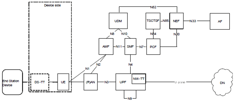
The 5G System architecture enables any Application Function (AF) - in the same or different trust domain - to provide its requirements for QoS, traffic characteristics for QoS scheduling optimization, time synchronization activation and deactivation.
If the AF is in a different trust domain from the 5G System, then it provides input via exposure framework, NEF API. If the AF is in the same trust domain as the 5G System, then it provides input directly via the Time Sensitive communication Time Synchronization function (TSCTSF).
The Functional Architecture is shown in the Figure below:

Figure 7.4-1: Architecture to enable Time Sensitive Communication and Time Synchronization services
(⇒ copy of original 3GPP image)
(⇒ copy of original 3GPP image)
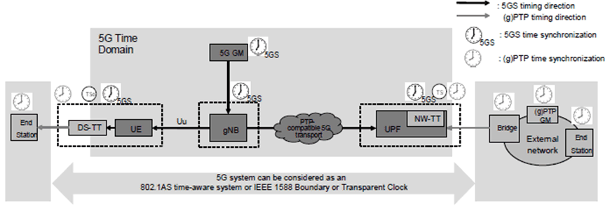
The Figure below depicts the two main synchronization methods supported: the 5GS synchronization and the (g)PTP domain synchronization.
- 5G Clock synchronization: Used for NG RAN synchronization and also distributed to the UE. 5G Clock synchronization over the radio interface towards the UE is specified in TS 38.331.
- (g)PTP synchronization: Provides time synchronization service to (g)PTP network. This process follows the standards IEEE Std 802.1AS or IEEE 1588 operation.

Figure 7.4-2: 5G system is modelled as PTP instance for supporting time synchronization
(⇒ copy of original 3GPP image)
(⇒ copy of original 3GPP image)
In order to support (g)PtP time synchronization, the 5G System operates in any of the following modes:
TSC Assistance Information (TSCAI) describes traffic characteristics that may be provided for use by the gNB, to allow more efficiently scheduled radio resources for periodic traffic and applying to PDU session type Ethernet and IP.
TSCAI describes TSC traffic characteristics for use in the 5G System. The knowledge of TSC traffic pattern is useful for 5G-AN to allow it to more efficiently schedule periodic and deterministic traffic flows either via Configured Grants, Semi-Persistent Scheduling or with Dynamic Grants.
- as time-aware system (IEEE Std 802.1AS).
- as Boundary Clock (IEEE Std 1588).
- as peer-to-peer Transparent Clock (IEEE Std 1588).
- as end-to-end Transparent Clock (IEEE Std 1588).
| Assistance Information | Description |
|---|---|
| Flow Direction | The direction of the TSC flow (uplink or downlink). |
| Periodicity | It refers to the time period between start of two data bursts. |
| Burst Arrival Time (optional) | The latest possible time when the first packet of the data burst arrives at either the ingress of the RAN (downlink flow direction) or the egress interface of the UE (uplink flow direction). |
| Survival Time (optional) | Survival Time, as defined in TS 22.261, is synonymous with the time period an application can survive without any data burst. |
5GS determines TSC Assistance Container based on information provided by an AF/NEF and may provide it to PCF for IP type and Ethernet type PDU sessions.
The AF may provide the traffic pattern parameters such as Burst Arrival Time with reference to the ingress port, Periodicity, Flow Direction, Survival Time and Time domain to the NEF. The NEF forwards the received traffic pattern parameters to TSCTSF.
The AF trusted by the operator can be allowed to provide such traffic pattern parameters to TSCTSF directly. The TSCTSF is responsible for determining and forwarding these traffic pattern parameters in TSC Assistance Container to the SMF (via PCF).
Survival Time was also introduced as part of TSCAI in order for the AF to provide the time period an application can survive without any burst. It refers to the time that an application consuming a communication service may continue without an anticipated message. Maximum number of messages (message is equivalent to a burst) or in terms of time units. Single burst is expected within a single time period referred to as the periodicity.
References
Related CRs:
set "TSG Status = Approved" in: https://portal.3gpp.org/ChangeRequests.aspx?q=1&workitem=850012,880010,920024,910059,900008,910014,910060,910061,910062
7.5 Support of reduced capability NR devices p. 60
| UID | Name | Acronym | WG | WID | WI rapporteur name/company |
|---|---|---|---|---|---|
| 900062 | Support of reduced capability NR devices | NR_redcap | RP-211574 | Ericsson | |
| 860035 | Study on support of reduced capability NR devices | FS_NR_redcap | R1 | RP-202704 | Ericsson |
| 900162 | Core part: NR_redcap | NR_redcap-Core | R1 | RP-211574 | Ericsson |
| 900262 | Perf. part: NR_redcap | NR_redcap-Perf | R4 | RP-211574 | Ericsson |
| 930018 | Architecture Enhancement for NR Reduced Capability Devices | ARCH_NR_REDCAP | S2 | SP-211100 | Aihua Li, China Mobile |
| 940005 | CT1 aspects of NR_redcap | ARCH_NR_REDCAP | C1 | CP-213081 | Chen Xu, China Mobile |
| 950047 | CT3 aspects of NR_redcap | ARCH_NR_REDCAP | C3 | CP-220304 | Chen Xu, China Mobile |
| 940100 | CT4 aspects of NR_redcap | ARCH_NR_REDCAP | C4 | CP-213081 | Chen Xu, China Mobile |
| 950044 | CT6 aspects of NR_redcap | ARCH_NR_REDCAP | C6 | CP-213081 | Chen Xu, China Mobile |
| 940027 | Charging aspects of Architecture Enhancement for NR Reduced Capability Devices | ARCH_NR_REDCAP | S5 | SP-211428 | Dong Jia, China Mobile |
Summary based on the input provided by Ericsson in RP-221163.
This Rel-17 work item introduces support for UE complexity reduction techniques and UE power saving techniques suitable for IoT use cases such as industrial wireless sensors, video surveillance, and wearables, with requirements on low UE complexity and/or low UE power consumption and with relatively relaxed data rate requirements. Following an initial study [1], this work item [2] specified support for a reduced capability (RedCap) UE type and two UE power saving techniques: Extended DRX in RRC idle/inactive state, and RRM measurement relaxation for neighbour cells.
The following key functionalities are introduced as part of this work item:
Reduced capability (RedCap) UE type:
SA2 have studied the architecture enhancement for NR RedCap and introduced the NR RedCap UEs differentiation requirement in clause 5.41 of TS 23.501. Accordingly, CT3 and CT4 have specified a new RAT type NR RedCap. Based on the conclusion, SA5 mainly focus on the charging requirement of 'RedCap NR Devices' or 'devices using NR RedCap', which can be used by operators to charge differentially.
Stage 2 work on WI ARCH_NR_REDCAP for TS 32.255, TS 32.256 and TS 32.274: Add charging requirement for SMF, AMF and SMSF to support NR RedCap, providing for NR RedCap UE using NR the RAT Type NR_REDCAP.
Stage 3 work on WI ARCH_NR_REDCAP for TS 32.298: Adding NR RedCap as a new RATType in CHF-CDR.
The new reduced capability (RedCap) UE type enables reduced UE complexity through various UE complexity reduction techniques. A RedCap UE supports a maximum UE Rx/Tx bandwidth of 20 MHz in FR1 and 100 MHz in FR2 (whereas a normal NR UE supports at least 100 MHz in FR1 and 200 MHz in FR2). A RedCap UE cannot support larger Rx/Tx UE bandwidths than 20 MHz in FR1 and 100 MHz in FR2, and it cannot support features related to carrier aggregation (CA), dual connectivity (DC), more than 2 UE Rx/Tx antenna branches, or more than 2 DL/UL MIMO layers.
A RedCap UE can furthermore have a reduced antenna configuration and a reduced number of DL MIMO layers:
Extended DRX in RRC idle/inactive state:
- For FR1, a RedCap UE supports 1 or 2 UE Rx branches and 1 or 2 DL MIMO layers. The supported number of DL MIMO layers is the same as the implemented number of Rx branches, and as a result, 2-Rx RedCap UEs have twice as high DL peak rate as 1-Rx RedCap UEs. The UE indicates to gNB how many branches/layers it supports. The gNB can allow or disallow access from 1-Rx and 2-Rx RedCap UEs separately per cell.
- For FR2, a RedCap UE can either support a legacy UE power class such as PC3 or the new lower UE power class PC7 (with a reduced-complexity reference UE Rx/Tx antenna configuration with either 1 panel with 4 elements or 2 panels with 2 elements each, corresponding to half the number of array elements compared to a legacy PC3 UE). Furthermore, the UE indicates support for 1 or 2 DL MIMO layers (independent of the antenna configuration).
Extended DRX cycles are introduced for RRC idle state (up to 10485.76 seconds, i.e., roughly 3 hours) and RRC inactive state (up to 10.24 seconds) as an optional feature for both RedCap and non-RedCap UEs. For use cases with relatively relaxed requirements on DL reachability/latency, the network may configure an extended DRX cycle, which may reduce the UE power consumption substantially during periods with large enough packet inter-arrival time.
RRM measurement relaxation for neighbour cells:
RRM measurement relaxation for neighbour cells is introduced as an optional feature for RedCap UEs that can be enabled by the network. In RRC idle/inactive states, to help reduce UE power consumption, the UE is allowed to further relax neighbour-cell RRM measurements (compared to existing Rel-16 relaxation functionality) when an RSRP/RSRQ-based stationarity criterion is met for a period of time, or when both the stationarity criterion and a not-at-cell-edge criterion are met. In RRC connected state, the network may configure the RSRP/RSRQ-based stationarity criterion and in that case the UE shall report when the criterion is met or no longer met (and how to use the reporting information is up to the network implementation).
Charging aspects (as per SP-220697 from China Mobile)
References
Related CRs:
set "TSG Status = Approved" in: https://portal.3gpp.org/ChangeRequests.aspx?q=1&workitem=860035,900162,900262,930018,940005,950047,940100,950044,940027
[7.5-1]
TR 38.875: V17.0.0, "Study on support of reduced capability NR devices"
[7.5-2]
RP-220966: "Revised WID on support of reduced capability NR devices"
[7.5-3]
RP-221162: "Status report for support of reduced capability NR devices"
[7.5-4]
TS 23.501: "System architecture for the 5G System (5GS)"
[7.5-5]
TS 32.255: "5G data connectivity domain charging"
[7.5-6]
TS 32.256: "5G connection and mobility domain charging"
[7.5-7]
TS 32.274: "Short Message Service (SMS) charging"
[7.5-8]
TS 32.298: "Charging Data Record (CDR) parameter description"
7.6 IoT and 5G access via Satellite/Non-Terrestrial (NTN) link p. 62
See the section "5G access via Satellite/Non-Terrestrial (NTN) link".
7.7 Charging enhancement for URLLC and CIoT p. 62
| UID | Name | Acronym | WG | WID | WI rapporteur name/company |
|---|---|---|---|---|---|
| 890020 | Charging enhancement for URLLC | 5G_URLLC | S5 | SP-200769 | Huawei, Chen Shan |
Summary based on the input provided by Huawei in SP-220571
As per the clause 5.33 of TS 23.501 the redundant transmission for high reliability communication to support Ultra Reliable Low Latency Communication (URLLC) is defined.
The WID 5G_URLLC specifies the charging principle, charging requirements, service operations and charging information for URLLC service charging, including:
- For dual connectivity based end to end Redundant User Plane Paths, SMF shall collect and report the usage for each redundant PDU session.
- For redundant transmission at N3/N9 interface and transport layer, the SMF shall collect and report the usage not counting redundant packets.
- QoS Monitoring to assist URLLC Service are reported.
References
Related CRs:
set "TSG Status = Approved" in: https://portal.3gpp.org/ChangeRequests.aspx?q=1&workitem=890020
| UID | Name | Acronym | WG | WID | WI rapporteur name/company |
|---|---|---|---|---|---|
| 940044 | Charging enhancements for 5G CIoT | 5G_CIoT_CH | S5 | SP-211448 | Zhu, Lei, Huawei |
Summary based on the input provided by Huawei in SP-220573.
This WID provides some charging enhancements for the 5GS CIoT features specified e.g. in TS 23.501 and TS 23.502. This 5GS CIoT charging is specified in TS 32.255. The support 5GS and EPC interwork scenarios are considered, as well as the roaming scenario. The charging information and CDR content are described in TS 32.291 and TS 32.298.
References
Related CRs:
set "TSG Status = Approved" in: https://portal.3gpp.org/ChangeRequests.aspx?q=1&workitem=940044
7.8 Messaging in 5G p. 63
| UID | Name | Acronym | WG | WID | WI rapporteur name/company |
|---|---|---|---|---|---|
| 930030 | Support of the 5GMSG Service | FS_5GMARCH | S6 | SP-200835 | Liu, Yue, China Mobile |
| 840036 | Study on support of the 5GMSG Service | FS_5GMARCH | S6 | SP-200835 | Liu, Yue, China Mobile |
| 890010 | Study on security aspects of the 5GMSG Service (St1 in Rel16) | FS_SEC_5GMSG | S3 | SP-200878 | Xiaoting Huang, China Mobile |
| 930005 | Security aspects of the 5GMSG Service | 5GMSG | S3 | SP-210835 | Xiaoting Huang, China Mobile |
| 930040 | Application Architecture for MSGin5G Service | 5GMARCH | SP-200832 | Liu, Yue, China Mobile | |
| 890026 | Application Architecture for MSGin5G Service | 5GMARCH | S6 | SP-200832 | Liu, Yue, China Mobile |
| 930004 | CT aspects for enabling MSGin5G Service | 5GMARCH | ct | CP-212106 | Liu, Yue, China Mobile |
| 930041 | CT1 aspects for enabling MSGin5G Service | 5GMARCH | C1 | CP-212106 | Liu, Yue, China Mobile |
| 930042 | CT3 aspects for enabling MSGin5G Service | 5GMARCH | C3 | CP-212106 | Liu, Yue, China Mobile |
Summary based on the input provided by China Mobile in SP-220285.
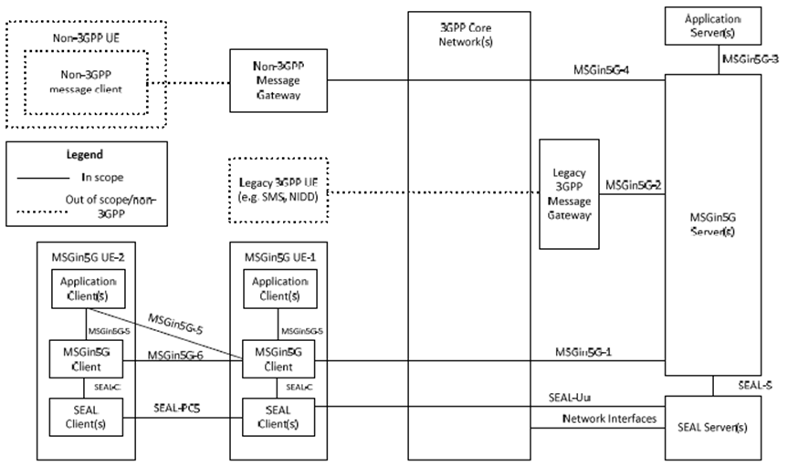
This Feature improves the messaging communication capability of the 5G System, especially for Massive Internet of Things (MIoT). It is based on the study in TR 23.700-24.
The following Figure, from TS 23.554, provides the high level illustration of the MSGin5G service:

The following functions are specified:
- Configuration of MSGin5G UE and Non-MSGin5G UE to get the MSGin5G Service configuration information (e.g. UE Service ID);
- Registration of MSGin5G UE and registration of Message Gateway on behalf of the Non-3GPP UEs;
-
Message delivery procedures for the message communication models listed below (the message can be delivered between different PLMNs):
- Point-to-point message which happens between a person and a thing or two things;
- Application-to-point message/ Point-to-application message which happens between an application server and an IoT device;
- Group message which originates at a UE and terminated at a group of UEs, all members in the group can send and receive the message;
- Broadcast message which originates at an application sever in the network or an UE and terminated at all the UEs in a specific service area within a cell or multiple cells;
- Message delivery based on messaging topic which the message is delivered to all subscribers (UE or Application Server) of this messaging topic.
- Message Aggregation can be used to optimize communications towards the same target by aggregating one or more messages into a single message;
- MSGin5G message can be segmented transmission if the content is larger than the maximum payload length of a message and reassembled by the suitable recipient;
- MSGin5G message can be stored by the MSGin5G Server if a UE is unavailable (disconnected or power off) for future delivery once the UE becomes available;
- 3GPP network functionalities of UE reachability status monitoring and device triggering can be leveraged by the MSGin5G Service via Core Network exposure.
- The Service Enabler Architecture Layer for Verticals (SEAL) capabilities "Group management service" and "Configuration management service" can be used by the MSGin5G service. These services are specified in TS 23.434 and TS 23.554.
References
Related CRs:
set "TSG Status = Approved" in: https://portal.3gpp.org/ChangeRequests.aspx?q=1&workitem=930030,840036,890010,930005,930040,890026,930004,930041,930042
[7.8-1]
TS 23.554: "Application architecture for MSGin5G Service; Stage 2" (specifies functional architecture, procedures, information flows and APIs )
[7.8-2]
TS 22.262: "Message Service within the 5G System".
[7.8-3]
TS 33.501: "Security architecture and procedures for 5G System".
[7.8-4]
TS 24.538: "Enabling MSGin5G Service; Protocol specification" (specifies detailed procedures over CoAP protocol between MSGin5G Client and MSGin5G Server)
[7.8-5]
TS 29.538: "Enabling MSGin5G Service; Application Programming Interfaces (API) specification;" (specifies the RESTful APIs provided by MSGin5G Server towards the Application Server and Message Gateway)
[7.8-6]
TS 23.434: "Service Enabler Architecture Layer for Verticals".
| UID | Name | Acronym | WG | WID | WI rapporteur name/company |
|---|---|---|---|---|---|
| 890001 | Service-based support for SMS in 5GC | SMS_SBI | CP-212023 | HAOUARI, Wafa, Orange | |
| 890028 | CT1 aspects of SMS_SBI | SMS_SBI | C1 | CP-212023 | HAOUARI, Wafa, Orange |
| 890029 | CT4 aspects of SMS_SBI | SMS_SBI | C4 | CP-212023 | HAOUARI, Wafa, Orange |
No summary was provided.