Content for TR 38.879 Word version: 18.0.0
A Failure Scenario from each contribution's view
A.1 Scenario and issue description (R3-224787)
A.2 Scenario (R3-224281)
A.3 Scenario and issue description (R3-224303)
A.4 Scenario and issue description (R3-224324)
A.5 Failure Case (R3-224576)
A.6 Scenario and issue description (R3-224627)
A.7 Scenario and issue description (R3-224754)
A.8 Scenario and issue description (R3-224898)
$ Change history
A Failure Scenario from each contribution's view p. 8
A.1 Scenario and issue description (R3-224787) p. 8
A.1.1 CU SW failure p. 8
Failure reason
gNB-CU-CP SW failure caused by software in gNB-CU-CP's equipment. This is mainly caused by information inconsistencies in the software, which in most cases can be resolved by restarting the system (or, in case of a virtualized implementation, by respawning the relevant software parts).
Failure impact
The impact of the failure and the extent of the restart depends on the configuration of the equipment and where the problem occurs. In some cases, the effect may be limited to only some functions in the gNB-CU-CP, while in other cases, all functions in the gNB-CU-CP may be affected.
A.1.2 gNB-CU-CP HW failure p. 8
Failure reason
gNB-CU-CP HW Failure is a problem caused by the hardware of the gNB-CU-CP, mainly due to aging and deterioration of the HW of the gNB-CU-CP, and in most cases can be resolved by replacing some of the HW in the equipment.
Failure impact
The impact of the failure and the extent of the replacement depends on the configuration of the equipment and the part of the problem. In some cases, only some functions of the gNB-CU-CP will be affected, but it is expected that the whole gNB-CU-CP will be affected, especially in the case of vRAN scenarios.
A.1.3 Power outages p. 8
Failure reason
Power outages are caused by power grid failures due to various disasters (earthquakes, lightning, tsunamis, fires, windstorms, snowstorms, etc.), as well as by malfunctions of substation equipment or cable breaks in the station building.
Failure impact
The impact of a failure depends on the part of the system where the failure occurs, but often affects multiple gNB-CU-CPs. The higher degree of centralization, the more gNB-CU-CPs will be affected.
A.1.4 Transport network failure (out of 3GPP scope) p. 8
Failure reason
Transport network failures result from cable breaks in transmission lines, network equipment failures, and misconfigurations. These can also occur as software or hardware malfunctions, disasters, or human error.
Failure impact
The impact of a failure depends on the part of the system where the failure occurs. When the failure occurs outside line, it often affects multiple gNB-CU-CPs. The higher degree of centralization, the more gNB-CU-CPs will be affected.
A.1.5 Summary of failure scenarios p. 9
Failures affecting only one gNB-CU-CP can be addressed by existing countermeasures.
For failures affecting multiple gNB-CU-CPs simultaneously, in particular when the cause of the failure is closely related to the region, such as a disaster, a solution that takes advantage of the different locations for deploying redundant infrastructure should be considered.
A.2 Scenario (R3-224281) p. 9
The most relevant scenarios in regard to gNB-CU-CP are those that will incur a failure of the entire gNB-CU-CP. Such cases would affect all the existing UE contexts under the gNB-CU-CP where the failure occurred. Likewise, the disaggregated gNB architecture allows for very large configurations. A given gNB-CU-CP can host 512 gNB-DUs, and a total of 16,384 cells with existing specifications. Furthermore, each cell may be serving hundreds of UEs Therefore, a gNB-CU-CP failure can incur a very high impact in service availability and user experience for a very large number of UEs. Further, these failure scenarios can incur further problems by generating very high signalling loads from e.g., re-establishment of connections and signalling interfaces.
In contrast issues affecting only limited portions of the gNB-CU-CP, for example, trouble incurred from individual hardware blades in a virtualized environment, are not the focus of this study.
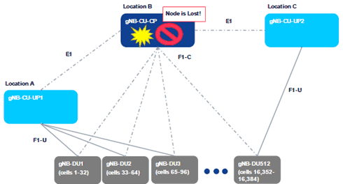
A.2.1 Scenarios A, B, C p. 9
(A) Node breakdown leading to a gNB-CU-CP failure
This failure scenario includes cases where the gNB-CU-CP becomes completely unresponsive. This could be e.g., due to hardware failure, or power source becoming lost and unrecoverable.
(B) Natural disaster leading to loss of the gNB-CU-CP
This failure scenario includes cases where the gNB-CU-CP becomes unrecoverable due to the node itself becoming destroyed or its required connectivity, hence becoming unrecoverable. This could be result of e.g., an earthquake, tsunami, or major fire.
(C) Human-made disaster leading to loss of the gNB-CU-CP
This failure scenario is similar to that caused by natural means but with the source of the failure being due to human involvement. This failure could be result e.g., of war, civil war, terrorism or social unrest.
A.2.2 Scenario D p. 10
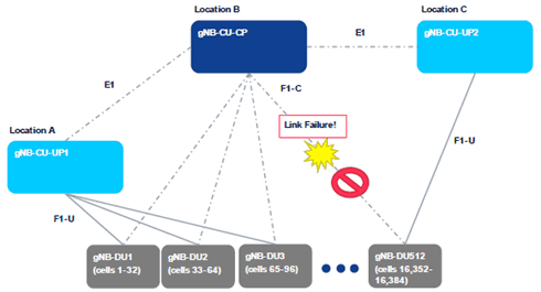
(D) Signalling Interface Link Failure
This failure includes cases where the control plane signalling link becomes unavailable. The issue may be temporary (e.g., intermittent issues at a switch/router at a given communication path), or (semi-)permanent.
A.2.3 Scenario E p. 10
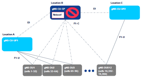
(E) Planned Maintenance Causing Downtime
This use case corresponds to maintenance events (e.g., Software upgrade, new feature activations, public protests or temporary unrest). Software upgrade may result in a full reboot of the gNB-CU-CP as well.
A.3 Scenario and issue description (R3-224303) p. 11
In the legacy network architecture, a gNB-CU-DU is only connected to one gNB-CU-CP. With the increasing number of connected gNB-CU-UP and gNB-DU, gNB-CU-CP will be in the risk of failure caused by the large amount of signalling processing. So this SI will introduce a mechanism to allow the gNB-CU-UP and gNB-DU to recovery service. Higher-layer split between gNB-CU and gNB-DU would enable highly-centralized gNB-CU deployment with large coverage area per gNB-CU, especially from C-Plane perspective. Likewise, Higher-layer split between gNB-CU-CP and gNB-CU-UP would enable highly-centralized gNB-CU-CP deployment with large coverage area per gNB-CU-CP.
As described in the draft SID, such a centralized gNB-CU(-CP) would be a single point of failure. Hence the resiliency of the gNB-CU(-CP) is highly important. Given the limited time allocated for gNB-CU resiliency, only gNB-CU-CP resiliency should be considered in this release, other network nod, e.g. AMF, gNB CU(non-split CU architecture) should not be considered in this release if time not allowed.
Failure condition:
Failure condition is the trigger of gNB-CU-CP resiliency. If a network node is considered a failure when it is crashed completely, then it would be too late to recovery. The network should have scheme to switch part or all of the services/connections to another resilient network node to offload before it completely crashes down. The decision of offloading the service/connection can be either of the below:
- Up to the implantation of gNB-CU-CP
- The configured threshold from OAM
A.4 Scenario and issue description (R3-224324) p. 11
The most critical cases are failures that may happen if a gNB-CU-CP is deployed in a central office location with responsibility for a high number of gNB-DUs and therefore of cells. There are different failure scenarios that may happen in such a deployment scenario:
- SW or HW failure in a PNF-based implementation;
- VNF (SW) or GPP (HW) failure in a virtualized environment (e.g. cloud-based implementation);
- Failures of NW connections, e.g., TN or server NW card failures;
- Total failure of central location, e.g., caused by a power shutdown or a disaster case.
- Outage of gNB-CU(-CP) when deployed in a central location without sufficient local redundancy, but availability of geo-redundancy (SW/HW) is given and fast recovery of gNB-CU(-CP) functionality is required by the operator.
A.5 Failure Case (R3-224576) p. 12
If a gNB-CU-CP fails, the network support for the NR cells is lost and UEs cannot communicate. More specifically, the following can be observed:
-
CP signaling redundancy is possible in RAN, but still only one RRC-anchor (gNB-CU-CP) is defined:
- SRB duplication is possible in DC (PDCP duplicates RRC messages, which are sent via different carriers to/from UE), but losing the main connection to the UE still means CP failure
-
RLF handling:
- Rel-15: if SCG connection fails, inform the network; if MCG fails, the connection is lost
- Rel-16: if SCG/MCG connection fails, inform the network via MCG/SCG. There will be MCG/SCG UP downtime due to DRBs suspension.
-
CP failure leading to UP failure (UP failure, leading to service interruption time, is probably the most important KPI associated with a CU-CP failure):
-
Generally, an absence of RRC messages is not noted by the UE, so the UE does not know that the CP has failed
- RRC timer expiry procedures in RRC work as long as RRC connectivity is up. In some cases DRBs suspension is caused by the expiration of timers
- If the gNB-CU-CP goes down, CP connectivity is not re-established automatically until the failure is detected
-
UP connection could be lost if RRC reconfiguration (critical to maintain UP) is not possible
- e.g. Handover required; bearer reconfiguration required; meet QoS or other RAN reconfiguration required
-
Generally, an absence of RRC messages is not noted by the UE, so the UE does not know that the CP has failed
A.6 Scenario and issue description (R3-224627) p. 12
A.6.1 Scenario #1: Geographical Redundancy p. 12
A.6.1.1 General description p. 12
Geographical redundancy is the distribution of mission-critical components or infrastructures, such as the servers across multiple data centers that reside in different geographic locations, which is able to ensures high availability and disaster recovery. Geographical redundancy will replicate the data and store it in other databases located in the separate physical locations. Even one of the locations fails or simply needs to be taken offline, the other location with the replicated data will not be affected.
Considering the geographical redundancy for gNB-CU-CP, the backup gNB-CU-CP could be allocated in the separate physical locations. In this case, even the original gNB-CU-CP detects the failures and cannot work, the appearance of the backup gNB-CU-CP is able to avoid the interruption of multiple UP traffic or the disconnection of multiple UEs.
A.7 Scenario and issue description (R3-224754) p. 13
A.7.1 Local Redundancy p. 13
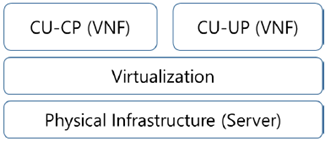
The split NG-RAN architecture consists of single logical gNB-CU-CP connected to multiple logical gNB-CU-UPs and multiple logical gNB-DUs, and the gNB-CU-CP is connected to multiple AMFs in 5GC. The logical gNB-CU-CP function can be implemented and deployed with the Network Function Virtualization as shown in Figure A.7.1-1. And the logical gNB-CU-CP function can be split further with sub-functions, e.g. network interface sub-function, and each sub-function can be implemented as a virtual network function component (VNFC).
A.7.2 Failure Scenarios p. 13
A.7.2.1 Server Failure p. 13
The server may not work properly because of hardware failure or virtualization platform failure. The hardware failure is caused owing to some deterioration or the instant failure of the hardware. Depending on the failure cause, the hardware needs to be replaced or be recovered by rebooting the system. The virtualization platform failure is caused by software error, so it could be also recovered by rebooting the system or by the software upgrade.
A.7.2.2 VNFC (Virtual Network Function Component) Failure p. 13
The logical gNB-CU-CP function can be implemented with sub-functions, e.g. network interface sub-function, and they can be separately implemented as VNFC (Virtual Network Function Component) and interact each other. One or more VNFCs consisting a gNB-CU-CP may not work properly owing to software error or other reason. Mostly the VNFC failure could be recovered by rebooting the system or by the software upgrade.
A.7.2.3 Transport Link Failure (out of 3GPP scope) p. 13
Transport link failure is caused by the malfunction of transport link hardware or software. The failure also comes from the transmission line problem or the transport network equipment failure. If the transport link failure caused in the gNB-CU-CP system, the failure could be recovered by rebooting the system or by the software upgrade. If the failure caused outside the gNB-CU-CP system, the transmission line needs to be substituted or the network equipment needs to be rebooted, upgraded or substituted.
A.7.3 Failure Impact p. 13
In any failure scenarios, there exist solutions to recover the logical gNB-CU-CP operation, e.g. system reboot, software upgrade, hardware replacement. Depending on the recovery solution, it may take a few minutes or some days and it may break the service continuity of the gNB-CU-CP.
So to minimize the interruption of UP traffic and disconnection of UEs, the virtualized gNB-CU-CP function could be duplicated, and the data used is shared and synchronized between duplicated gNB-CU-CP function. And if a failure is detected, the role of duplicated gNB-CU-CP functions are exchanged to support fast switch-over by implementation.
A.8 Scenario and issue description (R3-224898) p. 14
A.8.1 Possible failure scenarios p. 14
The purpose of this SI is to Study and identify failure scenarios associated with the gNB-CU-CP, based on the current architecture for the NG-RAN, which could be referred in 38.401 [2], see below:
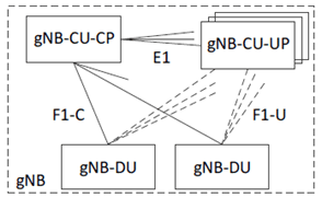
Figure A.8.1-1: Overall architecture for separation of gNB-CU-CP and gNB-CU-UP
(⇒ copy of original 3GPP image)
(⇒ copy of original 3GPP image)
gNB-CU-CP as a logical node, could be deployed in different way which is up to operator and vendor's strategy, e.g. could be software plus dedicated hardware within a physical box or, could be software instance run over virtualized environment (generic hardware). Thus, the failure could happen at any single point distributed at any place in Figure A.8.1-1, i.e. either to software or to hardware which would finally lead to the unavailable of gNB-CU-CP; in addition, power is also a main factor causing failure.