Content for TR 38.848 Word version: 18.0.0
4 Deployment scenarios, use cases, services
4.1 Use cases/services
4.1.1 Representative use cases
4.2 Deployment scenarios and connectivity topologies
4.2.0 Introduction
4.2.1 Connectivity topologies
4.2.1.0 Introduction
4.2.1.1 Topology 1: BS ↔ Ambient IoT device
4.2.1.2 Topology 2: BS ↔ intermediate node ↔ Ambient IoT device
4.2.1.3 Topology 3: BS ↔ assisting node ↔ Ambient IoT device ↔ BS
4.2.1.4 Topology 4: UE ↔ Ambient IoT device
4.2.2 Deployment scenarios
4.2.2.1 Deployment scenario 1: Device indoors, basestation indoors
4.2.2.2 Deployment scenario 2: Device indoors, basestation outdoors
4.2.2.3 Deployment scenario 3: Device indoors, UE-based reader
4.2.2.4 Deployment scenario 4: Device outdoors, basestation outdoors
4.2.2.5 Deployment scenario 5: Device outdoors, UE-based reader
4.3 Device categorization
...
...
4 Deployment scenarios, use cases, services p. 8
4.1 Use cases/services p. 8
4.1.1 Representative use cases p. 8
Two sets or levels of grouping were defined. The first, Grouping A, is on the basis of the deployment environment(s) described for a use case in TR 22.840 [2], and the second, Grouping B, is on the basis of functionality/application described in TR 22.840 [2].
Grouping A:
- Indoor
- Outdoor
- Indoor/outdoor
- Inventory
- Sensors
- Positioning
- Command
- rUC1: Indoor inventory
- rUC2: Indoor sensors
- rUC3: Indoor positioning
- rUC4: Indoor command
- rUC5: Outdoor inventory
- rUC6: Outdoor sensors
- rUC7: Outdoor positioning
- rUC8: Outdoor command
| rUC | Applicable SA1 UCs / traffic scenarios |
|---|---|
| rUC1: Indoor inventory | 5.1 Automated warehousing
5.2 Medical instruments inventory management and positioning 5.4 Non-Public Network for logistics 5.5 Automobile manufacturing 5.7 Airport terminal / shipping port 5.15 Smart laundry 5.16 Automated supply chain distribution 5.18 Fresh food supply chain 5.27 End-to-end logistics 6.1 Flower auction 6.3 Electronic shelf label |
| rUC2: Indoor sensor | 5.6 Smart homes
5.13 Base station machine room environmental supervision 5.15 Smart laundry 5.20 Smart agriculture 5.23 Smart pig farm 6.2 Cow stable |
| rUC3: Indoor positioning | 5.8 Finding Remote Lost Item
5.9 Location service 5.10 Ranging in a home 5.12 Personal belongings finding 5.14 Positioning in shopping centre 5.21 Museum Guide |
| rUC4: Indoor command | 5.11 Online modification of medical instruments status
5.17 Device activation and deactivation 5.26 Elderly Health Care 5.29 Device Permanent Deactivation 6.3 Electronic shelf label |
| rUC5: Outdoor inventory | 5.2 Medical instruments inventory management and positioning
5.4 Non-public network for logistics 5.7 Airport terminal / shipping port 5.16 Automated supply chain distribution |
| rUC6: Outdoor sensor | 5.3 Smart grids
5.19 Forest Fire Monitoring 5.22 Dairy farming 5.24 Smart manhole cover safety monitoring 5.25 Smart bridge health monitoring |
| rUC7: Outdoor positioning | 5.8 Finding remote lost item
5.9 Location service 5.12 Personal belongings finding |
| rUC8: Outdoor command | 5.11 Online modification of medical instruments status
5.17 Device activation and deactivation 5.26 Elderly Health Care 5.30 Controller in smart agriculture |
4.2 Deployment scenarios and connectivity topologies p. 10
4.2.0 Introduction p. 10
Deployment scenarios for Ambient IoT have been studied on the basis of a list of characteristics, and the representative use case(s) applicable to a scenario. The possible descriptions of the characteristics are as follows:
| Characteristic | Possible description entries |
|---|---|
| Environment (of the device) | Indoor
Outdoor Indoor or outdoor |
| Basestation characteristic (if any) | Macro-cell-based deployment
Micro-cell-based deployment Pico-cell-based deployment None |
| Connectivity topology | See clause 4.2.1 |
| Spectrum | Licensed FDD
Licensed TDD Unlicensed |
| Coexistence with existing 3GPP technologies | Deployed on the same sites as an existing 3GPP deployment corresponding to the basestation type. Deployed on new sites without an assumption of an existing 3GPP deployment. |
| Traffic assumption | Device-terminated (DT) Device-originated (DO) DO traffic includes DO autonomous (DO-A), and DO device-terminated triggered (DO-DTT) |
| Device characteristic | See clause 4.3:
Device A Device B Device C |
The study has considered Ambient IoT deployments in-band to NR, in guard-band of NR, and in standalone band from NR.
4.2.1 Connectivity topologies p. 11
4.2.1.0 Introduction p. 11
The following connectivity topologies for Ambient IoT networks and devices are defined for the purposes of the study. In all these topologies, the Ambient IoT device may be provided with a carrier wave from other node(s) either inside or outside the topology. The links in each topology may be bidirectional or unidirectional.
BS, UE, assisting node, or intermediate node could be multiple BSs or UEs, respectively. The mixture of indoor and outdoor placement of such nodes is regarded as a network implementation choice. Account would need to be taken of potential impact on device or node complexity. In the connectivity topologies, this does not imply the existence of multi-hop assisting or intermediate nodes.
4.2.1.1 Topology 1: BS ↔ Ambient IoT device p. 12
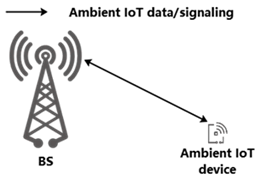
In Topology 1, the Ambient IoT device directly and bidirectionally communicates with a basestation. The communication between the basestation and the ambient IoT device includes Ambient IoT data and/or signalling. This topology includes the possibility that the BS transmitting to the Ambient IoT device is a different from the BS receiving from the Ambient IoT device.
4.2.1.2 Topology 2: BS ↔ intermediate node ↔ Ambient IoT device p. 12
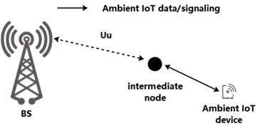
In Topology 2, the Ambient IoT device communicates bidirectionally with an intermediate node between the device and basestation. In this topology, the intermediate node can be a relay, IAB node, UE, repeater, etc. which is capable of Ambient IoT. The intermediate node transfers Ambient IoT data and/or signalling between BS and the Ambient IoT device.
4.2.1.3 Topology 3: BS ↔ assisting node ↔ Ambient IoT device ↔ BS p. 12
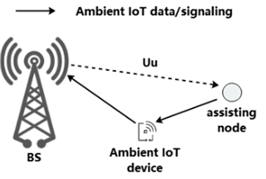
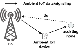
In Topology 3, the Ambient IoT device transmits data/signalling to a basestation, and receives data/signalling from the assisting node; or the Ambient IoT device receives data/signalling from a basestation and transmits data/signalling to the assisting node. In this topology, the assisting node can be a relay, IAB, UE, repeater, etc. which is capable of ambient IoT.
4.2.1.4 Topology 4: UE ↔ Ambient IoT device p. 13
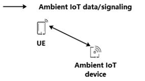
In Topology 4, the Ambient IoT device communicates bidirectionally with a UE. The communication between UE and the ambient IoT device includes Ambient IoT data and/or signalling.
4.2.2 Deployment scenarios p. 13
4.2.2.1 Deployment scenario 1: Device indoors, basestation indoors p. 13
With Ambient IoT device indoors and basestation indoors, this deployment scenario is characterized according to Table 4.2.2.1-1.
| Applicable representative use cases | Characteristics | Description (NOTE 1) |
|---|---|---|
| Indoor inventory
Indoor sensor Indoor positioning Indoor command | Environment (of device) | Indoor |
| Basestation characteristic (if any) | Micro- or pico-cell | |
| Connectivity topology | Topology (1), (2), (3) | |
| Spectrum | Licensed FDD, licensed TDD, unlicensed | |
| Coexistence with existing 3GPP technologies | Co-site or new site | |
| Traffic assumption | DT and DO | |
| Device characteristic | Device A or Device B or Device C |
4.2.2.2 Deployment scenario 2: Device indoors, basestation outdoors p. 14
With Ambient IoT device indoors and basestation outdoors, this deployment scenario is characterized according to Table 4.2.2.2-1.
| Applicable representative use cases | Characteristics | Description (NOTE 1) |
|---|---|---|
| Indoor inventory
Indoor sensor Indoor positioning Indoor command | Environment (of device) | Indoor |
| Basestation characteristic (if any) | Macro- or Micro- cell BS | |
| Connectivity topology | Topology (1), (2), (3) | |
| Spectrum | Licensed FDD, licensed TDD, unlicensed | |
| Coexistence with existing 3GPP technologies | Co-site or new site | |
| Traffic assumption | DT and DO | |
| Device characteristic | Device C may support Topology (1), (2), (3),
Device A may support Topology (2), Device B may support Topology (2), (3) |
4.2.2.3 Deployment scenario 3: Device indoors, UE-based reader p. 15
With Ambient IoT device indoors and UE-based reader, this deployment scenario is characterized according to Table 4.2.2.3-1.
| Applicable representative use cases | Characteristics | Description (NOTE 1) |
|---|---|---|
| Indoor inventory
Indoor sensor Indoor positioning Indoor command | Environment (of device) | Indoor |
| Basestation characteristic (if any) | None | |
| Connectivity topology | Topology (4) | |
| Spectrum | Licensed FDD, licensed TDD, unlicensed | |
| Coexistence with existing 3GPP technologies | NA | |
| Traffic assumption | DT and DO | |
| Device characteristic | Device A or Device B or Device C |
4.2.2.4 Deployment scenario 4: Device outdoors, basestation outdoors p. 15
With Ambient IoT device outdoors and basestation outdoors, this deployment scenario is characterized according to Table 4.2.2.4-1.
| Applicable representative use cases | Characteristics | Description (NOTE 1) |
|---|---|---|
| Outdoor inventory
Outdoor sensor Outdoor positioning Outdoor command | Environment (of device) | Outdoor |
| Basestation characteristic (if any) | Macro- or Micro- cell BS | |
| Connectivity topology | Topology (1), (2), (3) | |
| Spectrum | Licensed FDD, licensed TDD, or unlicensed. | |
| Coexistence with existing 3GPP technologies | Co-site or new site | |
| Traffic assumption | DT and DO | |
| Device characteristic | Device C may support Topology (1), (2), (3),
Device A may support Topology (2), Device B may support Topology (2), (3) |
4.2.2.5 Deployment scenario 5: Device outdoors, UE-based reader p. 16
With Ambient IoT device outdoors and UE-based reader, this deployment scenario is characterized according to Table 4.2.2.5-1.
| Applicable representative use cases | Characteristics | Description (NOTE 1) |
|---|---|---|
| Outdoor inventory
Outdoor sensor Outdoor positioning Outdoor command | Environment (of device) | Outdoor |
| Basestation characteristic (if any) | None | |
| Connectivity topology | Topology (4) | |
| Spectrum | Licensed FDD, licensed TDD, unlicensed | |
| Coexistence with existing 3GPP technologies | NA | |
| Traffic assumption | DT and DO | |
| Device characteristic | Device A or Device B or Device C |
4.3 Device categorization p. 16
Ambient IoT devices are characterized in the study according to their energy storage capacity, and capability of generating RF signals for their transmissions.
The study considers that a device has either:
- No energy storage at all; or
- Limited energy storage
- Device A: No energy storage, no independent signal generation/amplification, i.e. backscattering transmission.
- Device B: Has energy storage, no independent signal generation, i.e. backscattering transmission. Use of stored energy can include amplification for reflected signals.
- Device C: Has energy storage, has independent signal generation, i.e., active RF components for transmission.