Content for TS 38.351 Word version: 18.2.0
4 General
4.1 Introduction
4.2 SRAP architecture
4.2.1 General
4.2.2 SRAP entities
4.3 Services
4.3.1 Services provided to upper layers
4.3.2 Services expected from lower layers
4.4 Functions
4.5 Configurations
...
...
4 General p. 8
4.1 Introduction p. 8
The objective is to describe the SRAP architecture and the SRAP entities from a functional point of view.
4.2 SRAP architecture p. 8
4.2.1 General p. 8
This clause describes a model of the SRAP, i.e., it does not specify or restrict implementations.
4.2.2 SRAP entities p. 8
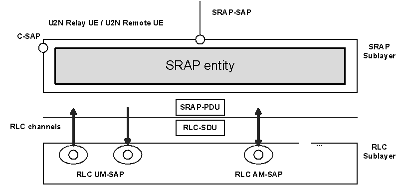
Figure 4.2.2-1 represents one possible structure for the SRAP sublayer. The Figure is based on the radio interface protocol architecture defined in TS 38.300.

On the U2N Relay UE, the SRAP sublayer contains one SRAP entity at Uu interface and a separate collocated SRAP entity at the PC5 interface. On the U2N Remote UE, the SRAP sublayer contains only one SRAP entity at the PC5 interface. On the U2U Relay UE and U2U Remote UE, the SRAP sublayer contains only one SRAP entity at the PC5 interface.
Each SRAP entity has a transmitting part and a receiving part. Across the PC5 interface in the U2N case, the transmitting part of the SRAP entity at the U2N Remote UE has a corresponding receiving part of an SRAP entity at the U2N Relay UE, and vice versa. Across the Uu interface, the transmitting part of the SRAP entity at the U2N Relay UE has a corresponding receiving part of an SRAP entity at the gNB, and vice versa.
Across the PC5 interface in the U2U case, the transmitting part of the SRAP entity at the U2U Remote UE has a corresponding receiving part of an SRAP entity at the U2U Relay UE, and vice versa.
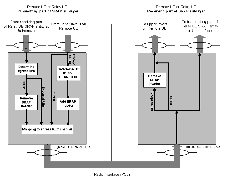
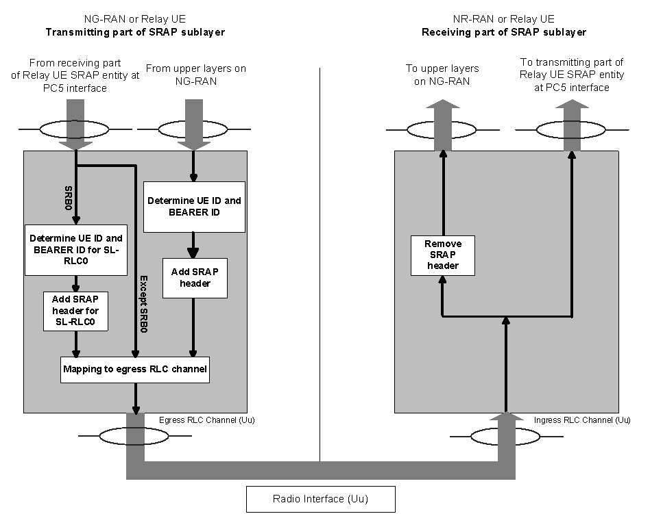
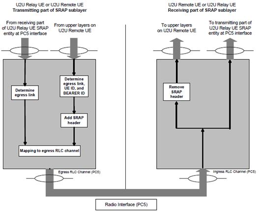
Figure 4.2.2-2 and Figure 4.2.2-3 represents the functional view of the SRAP entity in U2N Relay case for the SRAP sublayer at PC5 interface and at Uu interface respectively. Figure 4.2.2-4 represents the functional view of the SRAP entity in U2U Relay case for the SRAP sublayer at PC5 interface.

Figure 4.2.2-2: Example of functional view of SRAP sublayer at PC5 interface in U2N Relay case
(⇒ copy of original 3GPP image)
(⇒ copy of original 3GPP image)

Figure 4.2.2-3: Example of functional view of SRAP sublayer at Uu interface
(⇒ copy of original 3GPP image)
(⇒ copy of original 3GPP image)
In the example of Figure 4.2.2-2 and Figure 4.2.2-3, at relay UE:
- For data packet not corresponding to SRB0, the receiving part on the SRAP entity of Uu interface delivers SRAP Data PDUs to the transmitting part on the collocated SRAP entity of PC5 interface, and the receiving part on the SRAP entity of PC5 interface delivers SRAP Data PDUs to the transmitting part on the collocated SRAP entity of Uu interface. As an alternative, the receiving part may deliver SRAP SDUs to the transmitting part on the collocated SRAP entity. When passing SRAP SDUs, the receiving part removes the SRAP header and the transmitting part of the relay UE adds the SRAP header with the same SRAP header content as carried on the SRAP Data PDU header prior to removal. Passing SRAP SDUs in this manner is therefore functionally equivalent to passing SRAP Data PDUs, in implementation. The following specification therefore refers to the passing of SRAP data packets.
- For UL data packet corresponding to SRB0, the receiving part on the SRAP entity of PC5 interface delivers SRAP SDUs to the transmitting part on the collocated SRAP entity of Uu interface, and the transmitting part on the SRAP entity of Uu interface adds the SRAP header in accordance with clause 5.3.3.
- For DL data packet corresponding to SRB0, the receiving part on the SRAP entity of Uu interface delivers SRAP Data PDUs to the transmitting part on the collocated SRAP entity of PC5 interface, and the transmitting part on the SRAP entity of PC5 interface removes the SRAP header in accordance with clause 5.2.2. As an alternative for handling DL data packet corresponding to SRB0 not shown in Figure 4.2.2-2 or Figure 4.2.2-3, the receiving part on the SRAP entity of Uu interface removes the SRAP header and delivers SRAP SDUs to the transmitting part on the collocated SRAP entity of PC5 interface.

Figure 4.2.2-4: Example of functional view of SRAP sublayer at PC5 interface in U2U Relay case
(⇒ copy of original 3GPP image)
(⇒ copy of original 3GPP image)
In the example of Figure 4.2.2-4, at U2U relay UE:
- For U2U data packet, the receiving part on the SRAP entity of PC5 interface between the U2U Relay UE and the U2U Remote UE delivers U2U SRAP Data PDUs to the transmitting part on the SRAP entity of PC5 interface between the U2U Relay UE and the peer U2U Remote UE. As an alternative, the receiving part may deliver SRAP SDUs to the transmitting part on the SRAP entity. When passing SRAP SDUs, the receiving part removes the SRAP header and the transmitting part of the relay UE adds the SRAP header with the same SRAP header content as carried on the U2U SRAP Data PDU header prior to removal. Passing SRAP SDUs in this manner is therefore functionally equivalent to passing U2U SRAP Data PDUs, in implementation. The following specification therefore refers to the passing of SRAP data packets.
4.3 Services p. 11
4.3.1 Services provided to upper layers p. 11
The following services are provided by the SRAP sublayer to upper layers:
- Data transfer.
4.3.2 Services expected from lower layers p. 11
An SRAP sublayer expects the following services from lower layers per RLC entity (for a detailed description see TS 38.322):
- Acknowledged data transfer service;
- Unacknowledged data transfer service.
4.4 Functions p. 12
The SRAP sublayer supports the following functions:
- Data transfer;
- Determination of UE ID field and BEARER ID field for data packets;
- Determination of egress link;
- Determination of egress RLC channel.
4.5 Configurations p. 12
The configuration of the SRAP entity for U2N Remote UE includes:
- Mapping from a radio bearer identified by BEARER ID field to egress PC5 Relay RLC channel via RRC;
- The local identity via RRC.
- The local identity for each U2N Remote UE via RRC;
- Mapping from a radio bearer identified by UE ID field and BEARER ID field to egress Uu Relay RLC channel for each U2N Remote UE via RRC;
- Mapping from a radio bearer identified by UE ID field and BEARER ID field to egress PC5 Relay RLC channel for each U2N Remote UE via RRC.
- Mapping from a sidelink radio bearer identified by BEARER ID field to egress PC5 Relay RLC channel for each U2U Remote UE pair;
- The local identities.
- Mapping from a sidelink radio bearer identified by BEARER ID field to egress PC5 Relay RLC channel for each U2U Remote UE pair and each direction of data transfer.