Content for TS 38.322 Word version: 18.1.0
4 General
4.1 Introduction
4.2 RLC architecture
4.2.1 RLC entities
4.2.1.1 TM RLC entity
4.2.1.1.1 General
4.2.1.1.2 Transmitting TM RLC entity
4.2.1.1.3 Receiving TM RLC entity
4.2.1.2 UM RLC entity
4.2.1.2.1 General
4.2.1.2.2 Transmitting UM RLC entity
4.2.1.2.3 Receiving UM RLC entity
4.2.1.3 AM RLC entity
4.2.1.3.1 General
4.2.1.3.2 Transmitting side
4.2.1.3.3 Receiving side
4.3 Services
4.3.1 Services provided to upper layers
4.3.2 Services expected from lower layers
4.4 Functions
...
...
4 General p. 7
4.1 Introduction p. 7
The objective is to describe the RLC architecture and the RLC entities from a functional point of view.
4.2 RLC architecture p. 7
4.2.1 RLC entities p. 7
The description in this clause is a model and does not specify or restrict implementations.
RRC is generally in control of the RLC configuration.
Functions of the RLC sub layer are performed by RLC entities. For an RLC entity configured at the gNB, there is a peer RLC entity configured at the UE and vice versa. In NR sidelink communication, in NR sidelink discovery, for an RLC entity configured at the transmitting UE, there is a peer RLC entity configured at each receiving UE.
An RLC entity receives/delivers RLC SDUs from/to upper layer and sends/receives RLC PDUs to/from its peer RLC entity via lower layers.
An RLC PDU can either be an RLC data PDU or an RLC control PDU. If an RLC entity receives RLC SDUs from upper layer, it receives them through a single RLC channel between RLC and upper layer, and after forming RLC data PDUs from the received RLC SDUs, the RLC entity submits the RLC data PDUs to lower layer through a single logical channel. If an RLC entity receives RLC data PDUs from lower layer, it receives them through a single logical channel, and after forming RLC SDUs from the received RLC data PDUs, the RLC entity delivers the RLC SDUs to upper layer through a single RLC channel between RLC and upper layer. If an RLC entity submits/receives RLC control PDUs to/from lower layer, it submits/receives them through the same logical channel it submits/receives the RLC data PDUs through.
An RLC entity can be configured to perform data transfer in one of the following three modes: Transparent Mode (TM), Unacknowledged Mode (UM) or Acknowledged Mode (AM). Consequently, an RLC entity is categorized as a TM RLC entity, an UM RLC entity or an AM RLC entity depending on the mode of data transfer that the RLC entity is configured to provide.
A TM RLC entity is configured either as a transmitting TM RLC entity or a receiving TM RLC entity. The transmitting TM RLC entity receives RLC SDUs from upper layer and sends RLC PDUs to its peer receiving TM RLC entity via lower layers. The receiving TM RLC entity delivers RLC SDUs to upper layer and receives RLC PDUs from its peer transmitting TM RLC entity via lower layers.
An UM RLC entity is configured either as a transmitting UM RLC entity or a receiving UM RLC entity. The transmitting UM RLC entity receives RLC SDUs from upper layer and sends RLC PDUs to its peer receiving UM RLC entity via lower layers. The receiving UM RLC entity delivers RLC SDUs to upper layer and receives RLC PDUs from its peer transmitting UM RLC entity via lower layers.
An AM RLC entity consists of a transmitting side and a receiving side. The transmitting side of an AM RLC entity receives RLC SDUs from upper layer and sends RLC PDUs to its peer AM RLC entity via lower layers. The receiving side of an AM RLC entity delivers RLC SDUs to upper layer and receives RLC PDUs from its peer AM RLC entity via lower layers.
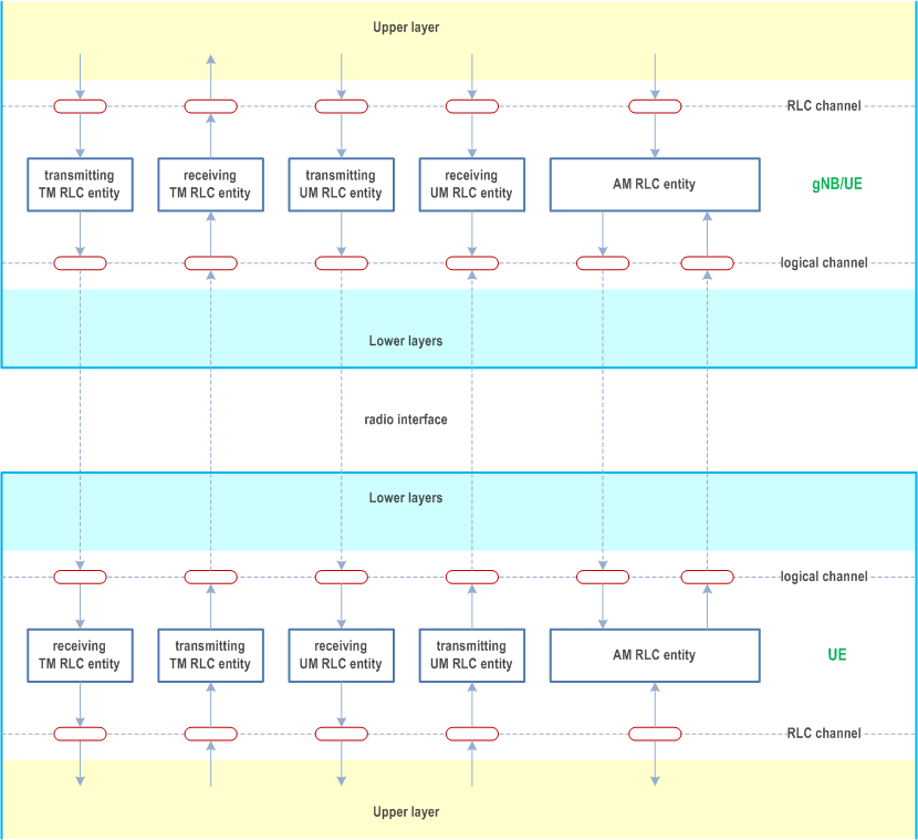
Figure 4.2.1-1 illustrates the overview model of the RLC sub layer.

RLC SDUs of variable sizes which are byte aligned (i.e. multiple of 8 bits) are supported for all RLC entity types (i.e. TM, UM and AM RLC entity).
Each RLC SDU is used to construct an RLC PDU without waiting for notification from the lower layer (i.e., by MAC) of a transmission opportunity. In the case of UM and AM RLC entities, an RLC SDU may be segmented and transported using two or more RLC PDUs based on the notification(s) from the lower layer.
RLC PDUs are submitted to lower layer only when a transmission opportunity has been notified by lower layer (i.e. by MAC).
Description of different RLC entity types are provided below.
4.2.1.1 TM RLC entity p. 9
4.2.1.1.1 General p. 9
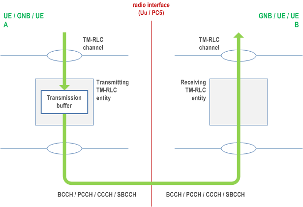
A TM RLC entity can be configured to submit/receive RLC PDUs through the following logical channels:
- BCCH, DL/UL CCCH, PCCH, and SBCCH.

A TM RLC entity submits/receives the following RLC data PDU:
- TMD PDU.
4.2.1.1.2 Transmitting TM RLC entity p. 9
When a transmitting TM RLC entity forms TMD PDUs from RLC SDUs, it shall:
- not segment the RLC SDUs;
- not include any RLC headers in the TMD PDUs.
4.2.1.1.3 Receiving TM RLC entity p. 9
When a receiving TM RLC entity receives TMD PDUs, it shall:
- deliver the TMD PDUs (which are just RLC SDUs) to upper layer.
4.2.1.2 UM RLC entity p. 9
4.2.1.2.1 General p. 9
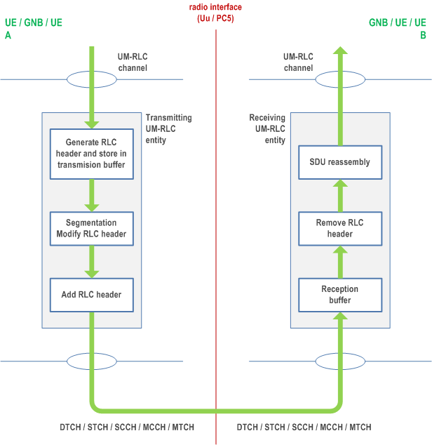
An UM RLC entity can be configured to submit/receive RLC PDUs through the following logical channels:
- DL/UL DTCH, SCCH, STCH, MCCH, and MTCH.

An UM RLC entity submits/receives the following RLC data PDU:
- UMD PDU.
4.2.1.2.2 Transmitting UM RLC entity p. 10
The transmitting UM RLC entity generates UMD PDU(s) for each RLC SDU. It shall include relevant RLC headers in the UMD PDU. When notified of a transmission opportunity by the lower layer, the transmitting UM RLC entity shall segment the RLC SDUs, if needed, so that the corresponding UMD PDUs, with RLC headers updated as needed, fit within the total size of RLC PDU(s) indicated by lower layer.
4.2.1.2.3 Receiving UM RLC entity p. 10
When a receiving UM RLC entity receives UMD PDUs, it shall:
- detect the loss of RLC SDU segments at lower layers;
- reassemble RLC SDUs from the received UMD PDUs and deliver the RLC SDUs to upper layer as soon as they are available;
- discard received UMD PDUs that cannot be re-assembled into an RLC SDU due to loss at lower layers of an UMD PDU which belonged to the particular RLC SDU.
4.2.1.3 AM RLC entity p. 11
4.2.1.3.1 General p. 11
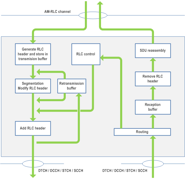
An AM RLC entity can be configured to submit/receive RLC PDUs through the following logical channels:
- DL/UL DCCH, DL/UL DTCH, SCCH, and STCH.

An AM RLC entity delivers/receives the following RLC data PDUs:
- AMD PDU.
- STATUS PDU.
4.2.1.3.2 Transmitting side p. 11
The transmitting side of an AM RLC entity generates AMD PDU(s) for each RLC SDU. When notified of a transmission opportunity by the lower layer, the transmitting AM RLC entity shall segment the RLC SDUs, if needed, so that the corresponding AMD PDUs, with RLC headers updated as needed, fit within the total size of RLC PDU(s) indicated by lower layer.
The transmitting side of an AM RLC entity supports retransmission of RLC SDUs or RLC SDU segments (ARQ):
- if the RLC SDU or RLC SDU segment to be retransmitted (including the RLC header) does not fit within the total size of RLC PDU(s) indicated by lower layer at the particular transmission opportunity notified by lower layer, the AM RLC entity can segment the RLC SDU or re-segment the RLC SDU segments into RLC SDU segments;
- the number of re-segmentation is not limited.
- include relevant RLC headers in the AMD PDU.
4.2.1.3.3 Receiving side p. 12
When the receiving side of an AM RLC entity receives AMD PDUs, it shall:
- detect whether or not the AMD PDUs have been received in duplication, and discard duplicated AMD PDUs;
- detect the loss of AMD PDUs at lower layers and request retransmissions to its peer AM RLC entity;
- reassemble RLC SDUs from the received AMD PDUs and deliver the RLC SDUs to upper layer as soon as they are available.
4.3 Services p. 12
4.3.1 Services provided to upper layers p. 12
The following services are provided by RLC to upper layer:
- TM data transfer;
- UM data transfer;
- AM data transfer, including indication of successful delivery of upper layers PDUs.
4.3.2 Services expected from lower layers p. 12
The following services are expected by RLC from lower layer (i.e. MAC):
- data transfer;
- notification of a transmission opportunity, together with the total size of the RLC PDU(s) to be transmitted in the transmission opportunity.
4.4 Functions p. 12
The following functions are supported by the RLC sub layer:
- transfer of upper layer PDUs;
- error correction through ARQ (only for AM data transfer);
- segmentation and reassembly of RLC SDUs (only for UM and AM data transfer);
- re-segmentation of RLC SDU segments (only for AM data transfer);
- duplicate detection (only for AM data transfer);
- RLC SDU discard (only for UM and AM data transfer);
- RLC re-establishment;
- Protocol error detection (only for AM data transfer).